I admit it: I'm a total geek. I love electronics, programming, 3D printing, 3D art, and vintage Apple hardware. I'm always juggling half a dozen projects. I also enjoy documenting it all: my successes, my failures, my experiences... and everything geeky along the way.
LCD Clock Version 2 - Part II | Kevin Rye.net - Main
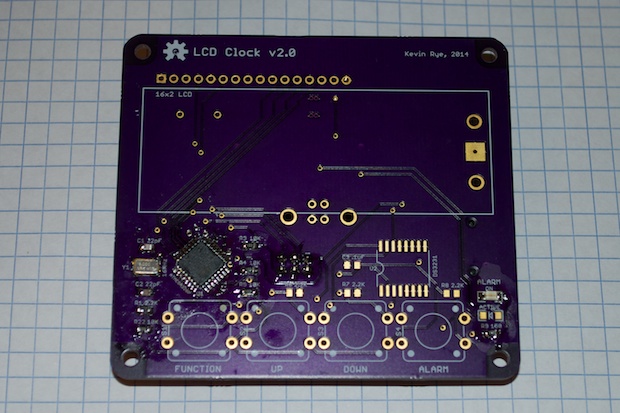
With my PCBs in-hand, and the laser cut acrylic on the way, it was time to start the assembly.
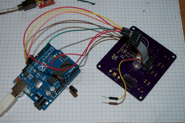
I started with the ATmega and all the components that were required to bootload the chip and upload my sketch. It would be a waste of components to install everything and find out that I made a mistake. It would also be that much harder to troubleshoot. It always makes sense to assemble your project in stages and test as you go.
Once all the components and headers were soldered in, I attached my Arduino and configured it as an ISP. I then burned the bootloader for an Arduino Uno.
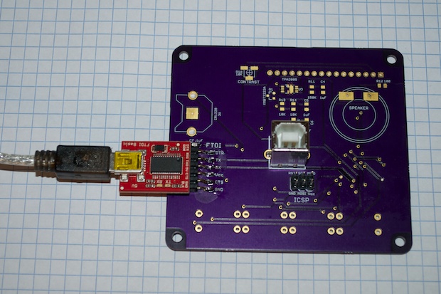
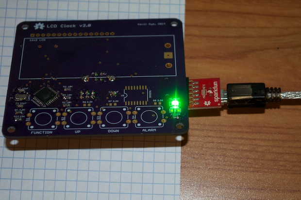
I then connected my FTDI programmer and uploaded the blink sketch.
Success!
Wow, that LED is super bright! It’s actually blinding and kind of hard to look at. With that, I swapped out the resistor for a 1K one in order to bring the brightness down.
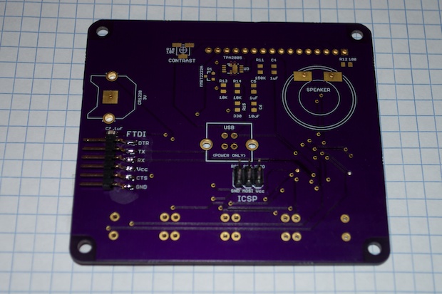
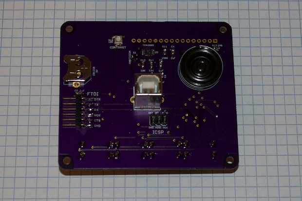
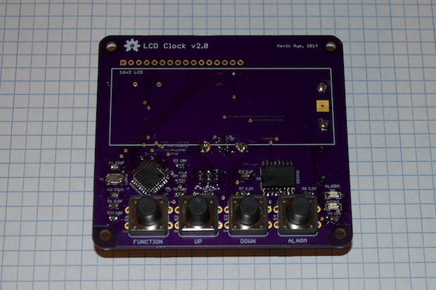
Knowing that the ATmega worked, it was time to solder in the rest of the components, except for the display. Again, I don’t want to come this far and then waste a $15 LCD.
I uploaded the Tone sketch and had it play a simple tune in order to test the audio. In this case, the Star Wars theme.
For the buttons, I configured the Alarm LED to flash with each button press to verify that everything was connected properly. Good to go. I then made sure that the ATmega could talk to the DS3231 RTC chip and set the time and date. Good to go.
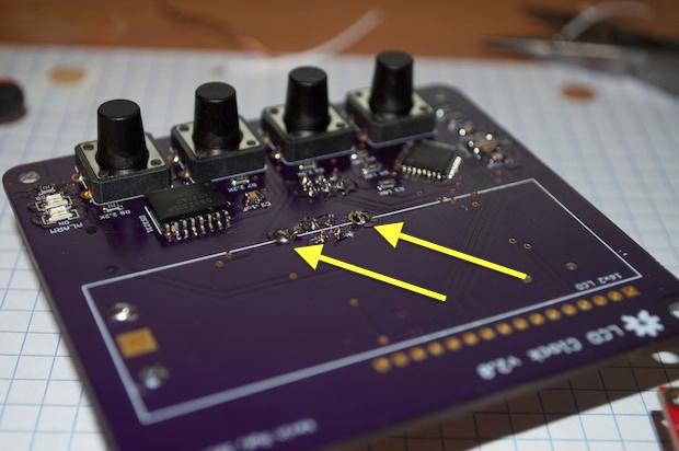
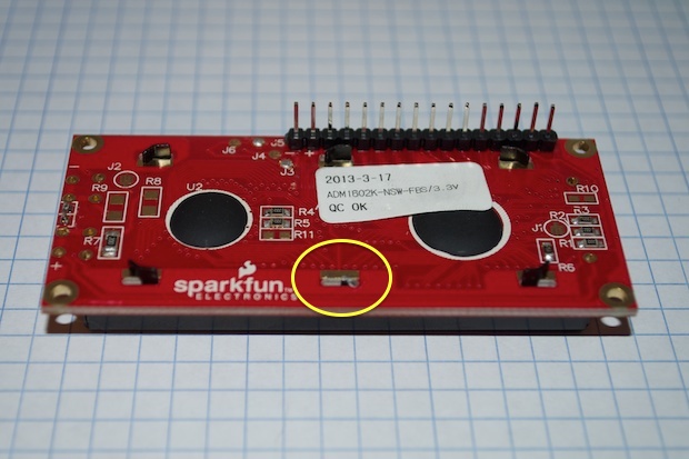
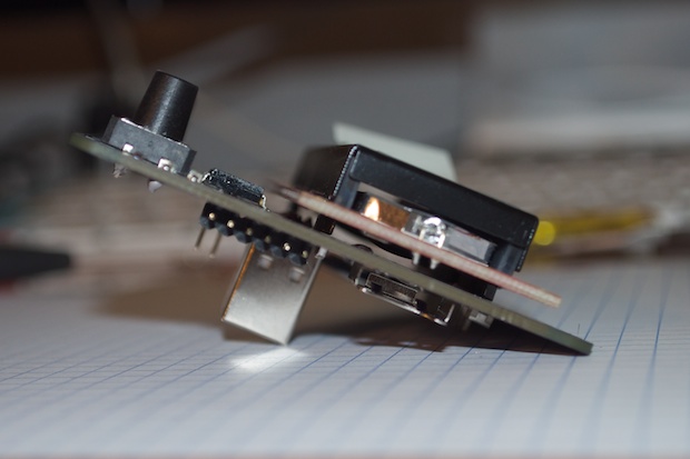
All that remained was the LCD. However, the large clips for the USB connector stuck up just a little higher than I had anticipated. They touched one of the clips on the back of the LCD, causing it to not sit flush against the PCB.
To solve that, I just cut that one clip off. No big deal.
The LCD then sat nice and flush against the PCB without contacting the USB connector.
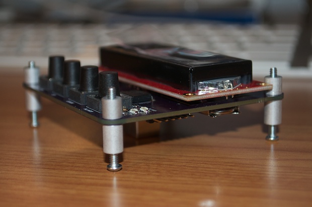
I still had some work to do on the code to implement the alarm feature, so until my acrylic arrived in the mail, I just threw a few standoffs on the clock so that it would sit nicely on my desk.
After a few hours of tweaking, I uploaded my final sketch that included an alarm menu, alarm tone, and chime-on-the-hour.
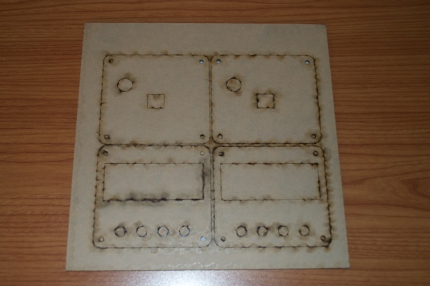
All that remained was the enclosure. My laser-cut acrylic showed up a few days later.
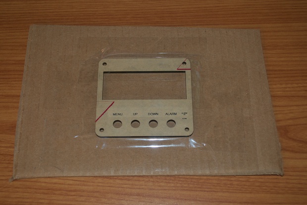
Looks pretty good.
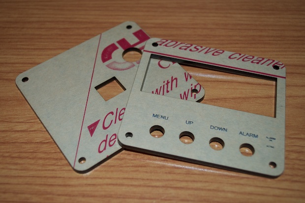
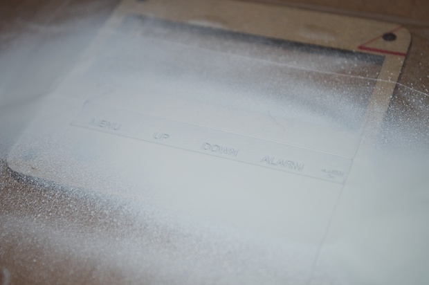
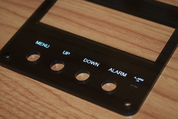
I masked off the engraved text.
I then gave it a quick blast of white spray paint.
It came out pretty good. The text for “ALARM ON” was a little too small for the paint to really get in there, so that didn’t come out perfect. I didn’t bother painting “ACTIVE” because that LED is always going to be on anyway, and it looks pretty white even without the paint. I was actually hoping that you wouldn’t be able to see it at all. The original intent was for that LED to only come on when the audio was active, but I forgot to wire the shutdown pin on the audio amplifier to the ATmega. So I couldn’t shut it down if I wanted to. Needless to say, that LED is always going to be on.
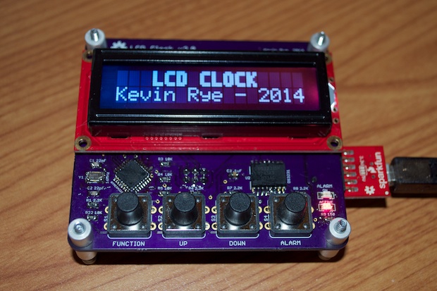
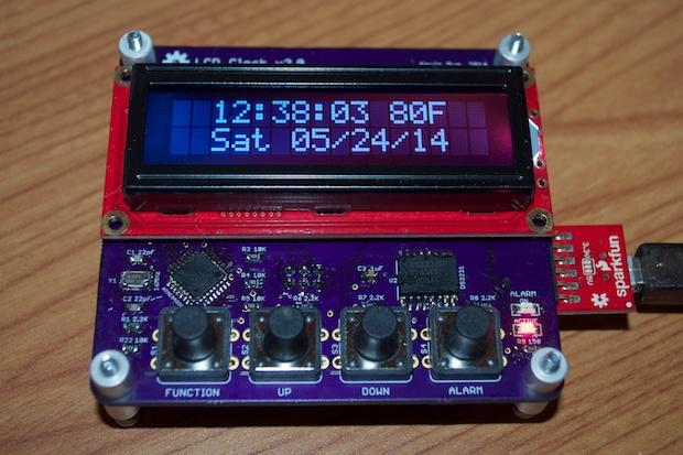
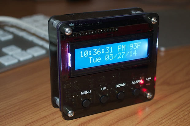
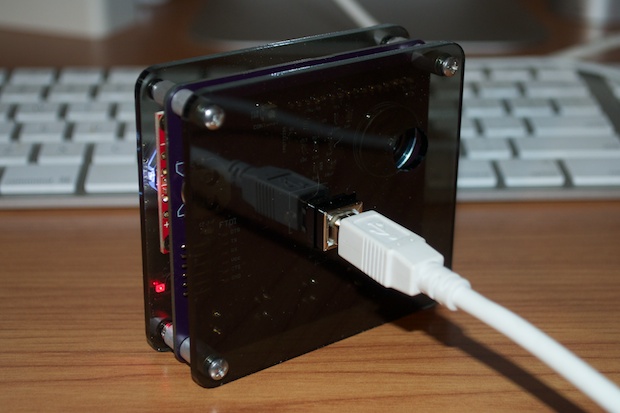
The final assembly.
I like how the text is easy to read on the dark acrylic, but it’s still easy to see the guts through it. It’s not black. It’s tinted gray.
Here it is in action. This short video shows the options in the functions menu, the alarm menu, the alarm going off, and the chime on the hour. Ideally, I’d like to save the alarm setting into the EEPROM, but I’ll leave that for another day. Another thing that needs to be tweaked is that the call to the Tone Library happens outside the main loop, so the clock stops counting while the alarm is going. Probably an easy fix, it’s just a matter for coding it.
I think this clock came out so much better than version 1. I can’t think of a reason to do a version 3. With this, I think I’ve done all I can do with a 16x2 LCD clock.