I admit it: I'm a total geek. I love electronics, programming, 3D printing, 3D art, and vintage Apple hardware. I'm always juggling half a dozen projects. I also enjoy documenting it all: my successes, my failures, my experiences... and everything geeky along the way.
Mini 7-Segment Clock, Part II | Kevin Rye.net - Main
I left off last time needing to write some code for the alarm setting feature. After a couple of hours of tinkering, I figured it out.
Pressing the alarm button displays the set alarm time. I did have the colon stop blinking while in set mode, but that must have been after I shot the video. Since I’m blinking the colon with the RTC’s 1Hz output, I just temporarily changed it to 4KHz while in set mode.
It’s hard to film the multiplexing. You’ll just have to trust me that it looks much better in real life. It worked out pretty well, but there’s a problem.
There’s no way the speaker is going to be loud enough to be much of an alarm. Here it is in action with a speaker much bigger than I planned on using.
Even if I add the SparkFun mono amp that I used for the SpeakJet board, I don’t know what use it’ll be. Maybe having an alarm feature is overkill. It seemed like a nice idea at the time, but once I saw it implemented, I realized it’s not worth it. The whole point of this clock was to keep it super tiny.
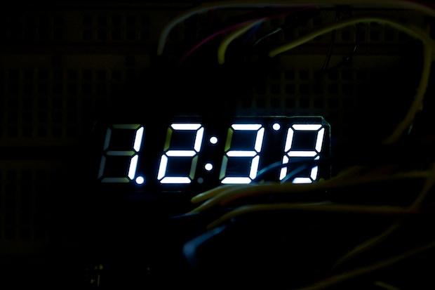
Another problem that I was having was the confusion between the PM and the “alarm set “ indicators.
Can you tell which is which?
I’ve never seen a clock where the PM indicator isn’t to the top-left of the display. It’s a weird display. They put a colon in the middle as to suggest it’s made for a clock, but a PM LED isn’t where you’d expect one to be.
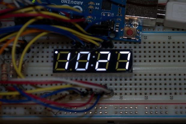
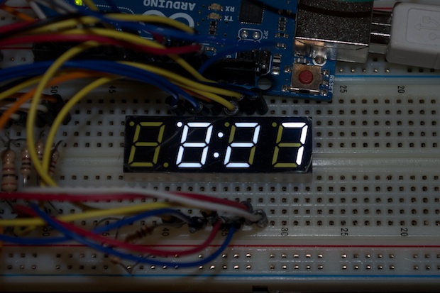
The solution? I flipped the display upside down. I just had to remap the pinouts in my code. Now the decimals are on the top. I can then light up the leftmost decimal to indicate “PM”.
Since I chose to turn off the left-most digit when the hours are less than 10:00, I just light up the next one over. That way the PM LED isn’t “floating” out there.
Since I’ve ditched the alarms, I don’t have to worry about implementing an indicator. Here’s the final code showing the AM/PM LED at work.
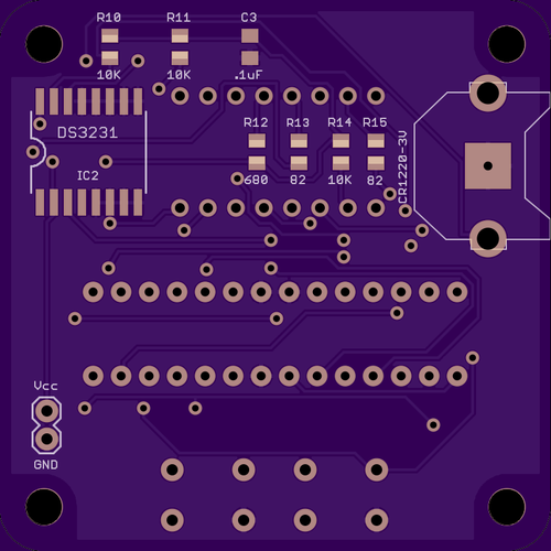
One last thing I wanted to do was trade the DS1307 for a DS3231. That required a slight code change since I’m using the 1 Hz out for the flashing colon.
Wire.beginTransmission(your_DS3231_address);
Wire.write(0x0E); // point to SQW address
Wire.write(0b00000000); // send 1Hz
Wire.endTransmission();
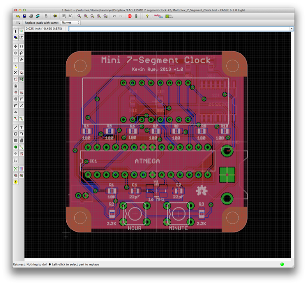
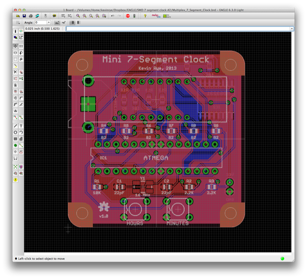
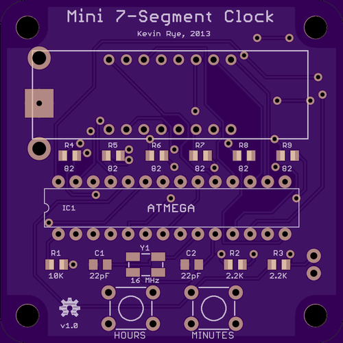
Since I’m ditching the alarm, I had to pull out all the alarm stuff from the PCB.
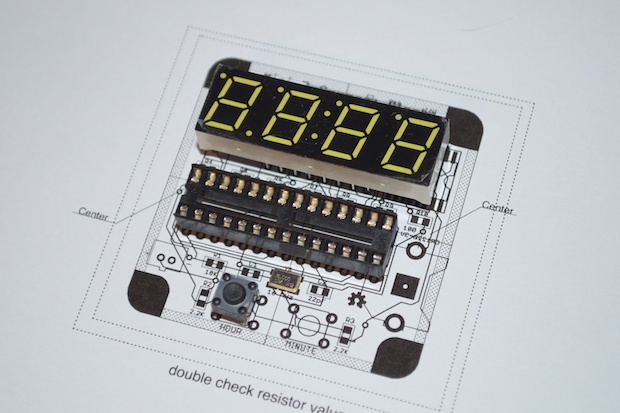
It was looking pretty good, so I printed it out just to see if it needed any last-minute tweaks.
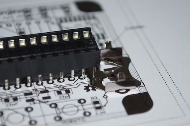
The spacing on the top looks pretty good, but there's something about that backup battery for the DS3231 that’s bothering me.
Once I placed the battery holder on the printout, it was pretty obvious that the pins from the ATmega will be touching the negative side of the battery. Oops! I’ve been paying so much attention to the SMD components and the fact that they can be on top of each other on opposing sides, that I almost overlooked this through-hole blunder. I figured since it was on the back that it wouldn’t be a problem where it was.
I had to redo the board so that the battery holder was behind the LED display. I could have just moved the ATmega over to the left, but I really wanted to keep it centered under the display. (I’m all about symmetry.)
All things considered, this was a pretty quick project. I know it’s been a long time coming, but once I started it, it only took me a week to complete the code and the PCB. I wasn’t expecting to finish this before the E-Paper Clock PCBs arrived.