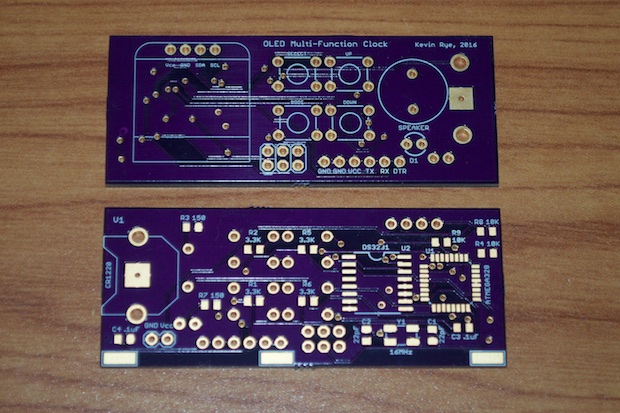
My Multi-Function OLED Clock PCBs arrived. It seemed like such a long wait this time. Maybe I'm just a little anxious to see if I got everything right. I have to admit, I am a little nervous that something's not going to work; not with the clock itself, but with the battery board.
Since I couldn't prototype it, I just had to cross my fingers and hope for the best. I hate sending off for a board not being 100% confident in my design.
If anything, this is a great chance for me to try out my
new reflow oven. I know that I should probably bake a few scrap boards first, but like I said, I'm anxious!
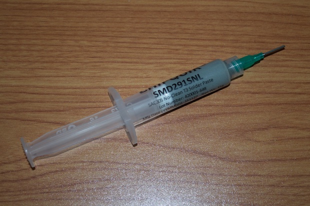
I grabbed some solder paste and applied a small blob to each pad. Now I know why people get solder paste dispensers. You really have to bear down on that plunger to get it to come out.
After all the pads had some solder paste, I placed my components. I designed these boards knowing that I'd be putting them in the oven. That's why there are no SMD-components on the back. Once the boards come out of the oven, all I'll have to do is solder a few PTH parts by hand.
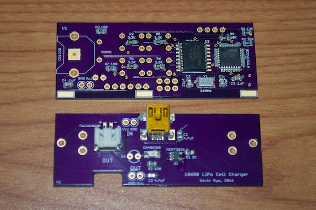
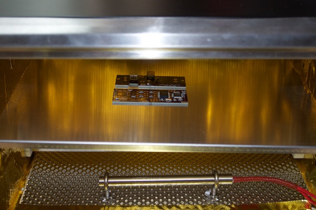
The boards went into the oven and came out a few minutes later. They look great.
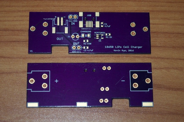
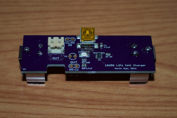
First up is the 18650 battery board. This is the one that I'm afraid isn't going to work.
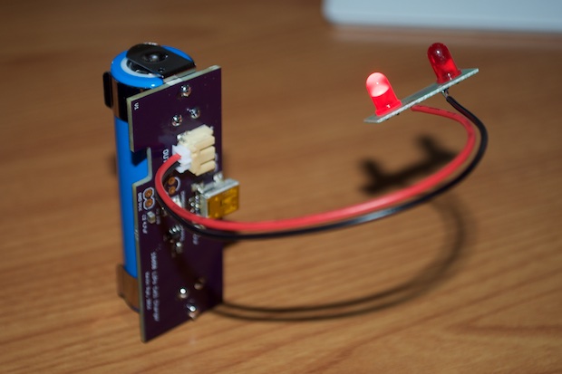
I connected a little blinky-LED board to the output and the LEDs started to blink, so I'm getting some juice. Maybe it'll work after all. I won't know for sure until I plug it in and see if it actually charges the battery, or lets the smoke out.
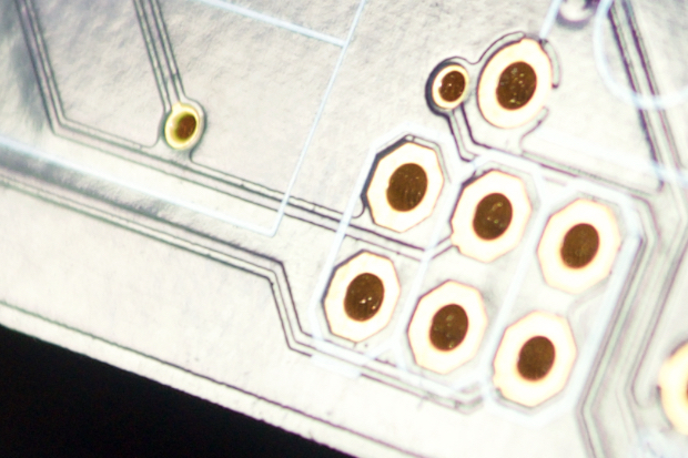
The main clock board is another story altogether. The one I put together doesn't work. Before I continued with the PTH parts, I attempted to bootload the chip. As soon as I connected my programmer, my Mac complained that the USB port was pulling too much current and disabled the port. That's a short. I measured the resistance across Vcc and ground and it was about 10K. That's weird. It should be in the meg-ohm range. There's a short somewhere.
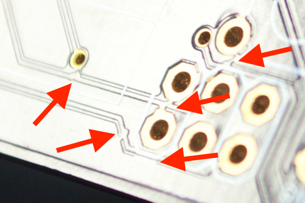
I reinspected the soldering for solder balls and bridges, etc., but everything looked perfect. I then took a closer look at the board itself. Nice going OSH Park! Look at all those shorted traces!
I've seen people complain about these kinds of errors from the cheap China fab houses, but never OSH Park.
The other two boards look perfect, so they must have had a bad panel. What a waste of time and components. I guess I could unsolder them and move them to another PCB, but that seems like a lot of unsoldering and cleanup for $4 bucks worth of parts.
Here’s what it’s supposed to look like.
I assembled another board, successfully bootloaded it, and uploaded the Blink sketch.
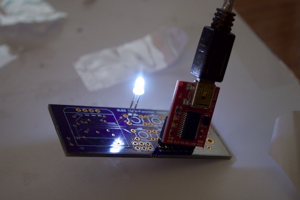
Once I knew I had a working board, I hand soldered the rest of the PTH parts.
Sweet! It works!
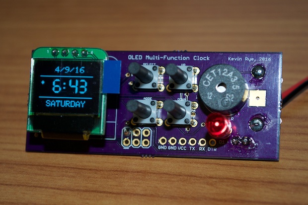
The weird thing is that the low-battery LED is on. Considering I have it connected to my breadboard, it should be getting 5V from my Arduino. Why is the low-battery LED on?
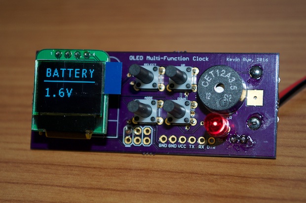
The Battery menu shows the voltage as 1.6V. I figured it has something to do with the fact that the code on the chip was written/calibrated for the ATmega328 on my Arduino Uno. I'll have to tweak the code based on the internal voltage reference on the clock’s ATmega328.
I have to admit, the 18650 battery board is rather embarrassing. I really don't know what I was on when I submitted that board. I found not one, not two, but three mistakes on the board; and real noobie stuff too. When I connected it to the clock, it worked, but only for a minute. The clock shut off and I smelled something burning. I immediately pulled the battery out. All the components looked OK, but the trace that connects the positive side of the battery to the JST-out connector is all burned up.
That's when I looked back over my Eagle file and saw that I had a trace to a ground pad not even connected. Let's not forget, I don't even know if I can even use this chip to charge an 18650. People call them "LiPos", but I've seen that they are sometimes called "lithium-polymer" and "lithium-ion". I've even seen "lithium-polymer-ion". So which is it? I've seen several sites use these terms interchangeably, while other sites claim that they are different. Some sites collectively refer to them all as "LiPos" while others state that LiPos are not Lithium-ion. It all seems very confusing.
So, did I let the smoke out because of a board error? Or because the 18650 and the MCP73831 aren't friends? I don't know if I should respin this board and find out, or just redo the board and use an actual "LiPo". I just love the fact that the 18650 has a 2600mAh capacity. I'd hate to go with a flat-pack that's twice the size, but half the capacity.
See this project from start to finish:
Mini OLED Clock - Part I Mini OLED Clock - Part II Mini OLED Clock - Part III
Mini OLED Clock - Part IV Mini OLED Clock - Part V Mini OLED Clock - Part VI
