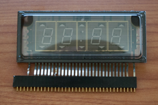
It’s been at least 6 months since I last played around with this
VFD. I had so many other projects in the works that I needed to finish first. I really want this clock to be something special, so I saved it for when all my other projects were complete. That, and I’m supposed to be saving my money since the holidays are right around the corner.
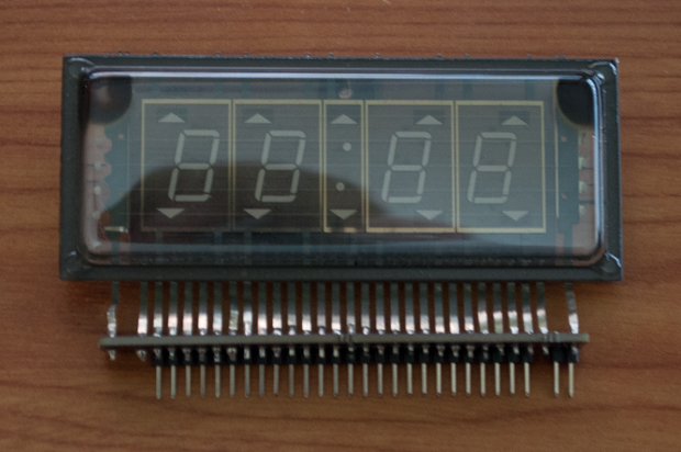
Instead of going nuts with a full-on build, I figured that I could at least breadboard something and play around with some code. However, getting this VFD in my breadboard is easier said than done. Trying to get all 30 pins in the breadboard at the same time (without bending the hell out of them) is no easy task. I tried to shove it into a female header and use that, but it just keeps popping out of the breadboard.
I figured I'd put together some kind of breakout board for it that I can plug into my breadboard. Hopefully once it's soldered on I'll still be able to somehow incorporate it into the final build. Once I solder it on, it's not coming off.
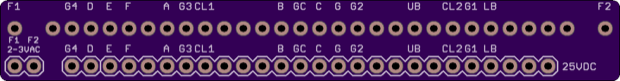
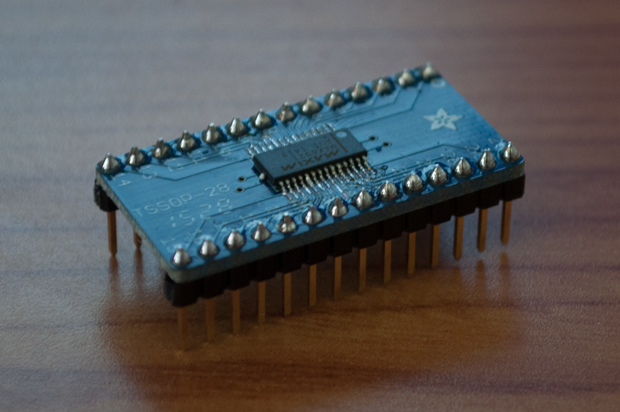
Rather than wait two weeks for the PCB to arrive, I attempted to prototype something using the DIY adapter. It's horrible, but hopefully it's good enough for me to at least get started.
The original plan was to drive the whole clock with a 20-output MAX6921 VFD driver chip.
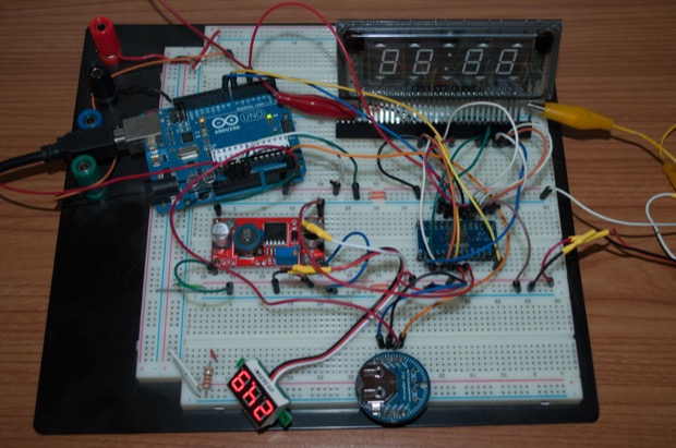
However, this chip is insane! I just can't figure it out. There's no shortage of code samples online for using it with an 8-digit IV-18 tube, but I couldn't find anything for a 4 digit VFD. I tried to modify some 8-digit code to fit the display, but I couldn't get it to do anything.
See? Here's a picture of it doing nothing.
Since the grids and the segments need 25V, I guess I need to drive the whole thing with transistors. Four grids, seven segments, the colon, the PM indicator: that's 13 transistors. Wow!
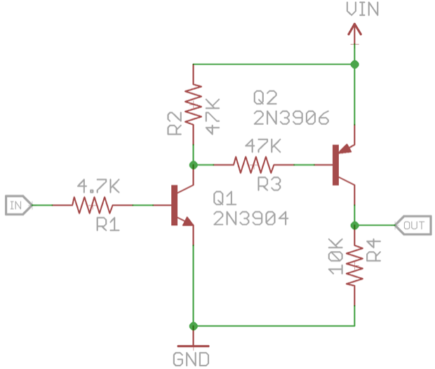
I started to put something together on my breadboard when it hit me. I'm using my default goto transistor… the 3904….but those are NPNs. This VFD is a common anode display, so I'll need to use PNPs. The problem with that is, if the voltage you need to switch is higher that the 5V that the Arduino can handle, you'll let the magic blue smoke out. Since PNPs are "backwards" you have to put the supply voltage on the base to turn it off. The base would be connected to an output on the Arduino. That's bad!
So how do I fix this? High-side switching. I'll need to have the Arduino turn on a NPN transistor, which will then turn on a PNP transistor.
My transistor count just doubled to 26! Double wow! I think this clock is going to be a little bigger than I planned; unless I go all SMD. Since the VFD is vintage, I wanted to go all through-hole with the components to keep the overall look old school.
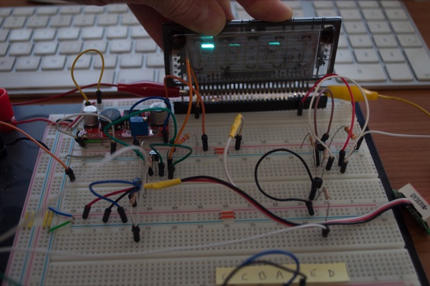
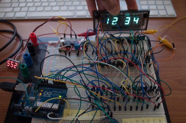
Before I make any decisions, I figured I'd at least test my schematic. I wired up one grid and one segment and uploaded a quick little sketch. It's basically the blink sketch. I just have to switch the grid high, and toggle the segment.
Success! (The ghosting on the other digits is due to the fact that the filament is DC powered. I'll have to make something to power it with AC.)
Here it is in action:
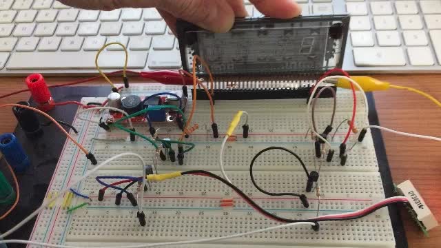
See? I have to hold the display in place while it's powered so it doesn't pop out.
I then wired up another NPN and PNP to each grid and segment. Damn, that's a lot of wires!
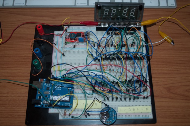
I said I wasn't going to go nuts with a full-on build, and that I was just going to try and breadboard something and play around with some code. I didn't realize it was going to be this easy. I breadboarded the circuit in about an hour. I then recycled the code I wrote for my
Large 7-Segment LED Clock.
Nailed it!
Lucky, my breakout board arrived 2 days later.
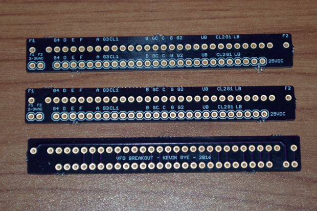
It's perfect.
There's no way it's coming out now. It makes it so much easier to push on with the code. I was able to add my mini button breakout board and get the code for setting the clock working.
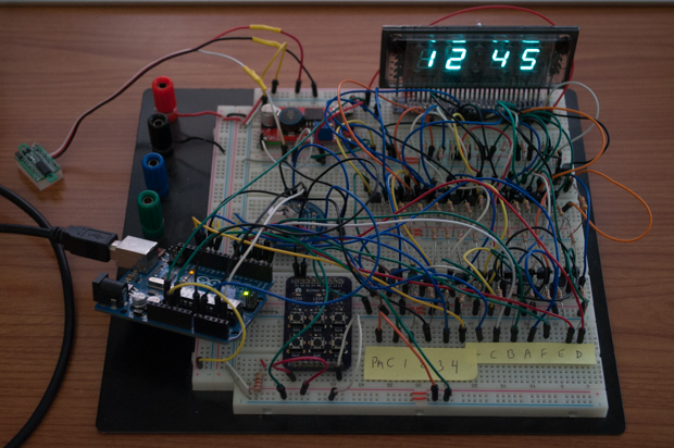
All I need to do is figure out how I'm going to flash the colon (probably use the 1Hz square wave out on the DS3231) and play around with the code for the PM indicator.
After that, I'll just need to finalize the schematic and I can then get to work on the PCB.
See this project from start to finish:
I Finally Figured Out This Vacuum Fluorescent Display VFD Clock - Part I
VFD Clock - Part II VFD Clock - Part III VFD Clock - Part IV VFD Clock - Part V VFD Clock - Part VI Clock Button Panels
