I had to get through the busy holiday season before I could get the ball rolling again. I've taken a long enough break from my hobby stuff. It’s been a few months since I’ve stretched the engineering muscles, so it's time to get back into things.
One project I've been meaning to revisit for well over a year is my
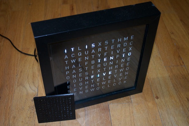
Word Clock.
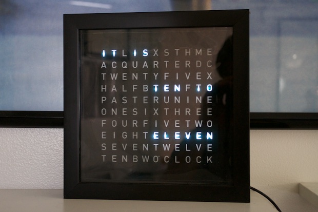
I recently had one of my readers build his own based off my design. It came out
perfectly. I helped him out and gave him a few pointers along the way. It was only the second Arduino project I did, so my documentation wasn't perfect. I designed my Word Clock several years ago. I have learned so much since then that I wanted to have a crack at a Word Clock 2, and apply a lot of the new things that I've learned. Mainly, SMD technology and 3D printing.
The display panel for my first Word Clock was as big as it needed to be in order to accommodate 96 through-hole LEDs, 96 resistors, and all the necessary wiring.
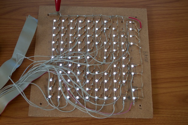
Any smaller, and it would have been really hard to accomplish the necessary soldering, if not impossible. I always wished it could have been smaller, but I was limited by the size of the LEDs, the resistors, and the sheer amount of wire involved.
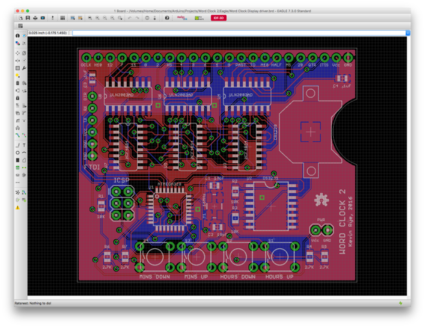
The original plan for version 2.0 was to basically take the existing schematic, convert all the parts to SMD, and downsize everything. That would work for the controller board, but there wasn't a PCB for the display. I'd have to design that from scratch.
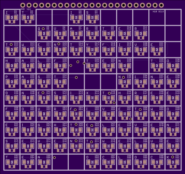
I tried to make it as small as possible, while still using 1206 LEDs. I considered using 603s, but in the end I thought they'd be either too small to work with, or not bright enough. That, and that the clock would be so small, it would be extremely difficult to construct the baffles that would isolate one LED from the other.
I tried to limit all the traces from the LEDs and resistors to the top side of the board and place the controller board components on the back. Unfortunately, there was just no way to do it. With everything being SMD, I'd need so many vias, that there just wasn't enough real estate to pull it off. Maybe with a 4-layer board I could have made it work, but it's not worth the added expensive.
The only solution was to make two PCBs. This is the final design for the display board. I incorporated a 23-pin header in order to connect the display board to the controller board.
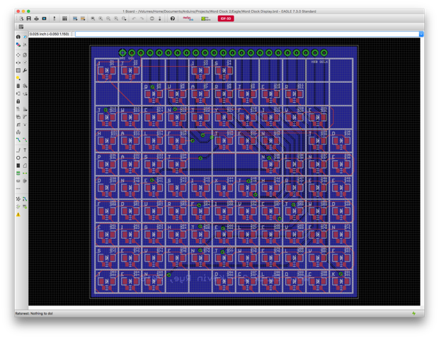
Although I managed to make it pretty small, it'll still cost $40.55 to have 3 boards made by OSH Park. They measure 70mm x 75mm.
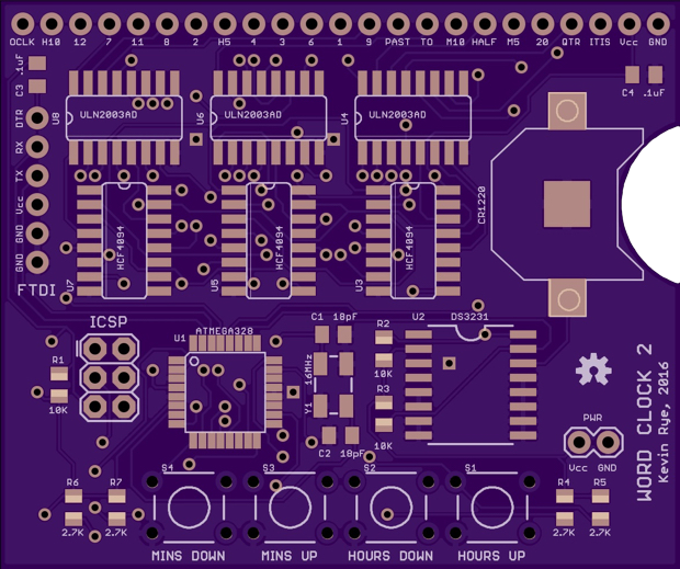
Version 1 of the clock only had two set buttons. One button to advance the clock forward and one to go back. I figured it wasn't a big deal. It does take forever to set the clock. It has a battery backup, so I figured you set the clock once and your done. However, for daylight savings, I just want to press a button once to go back or forwards an hour, and not have to step though "IT IS FIVE PAST....IT IS TEN PAST....IT IS QUARTER PAST...etc". I thought having buttons for both hours and minutes would be an obvious feature addition to a rev 2 Word Clock.
Other than the four pushbuttons, all the other components were changed to SMD versions. Well, all but the headers obviously. I also incorporated an ICSP and FTDI header. I also put in a little cutout on the PCB to make inserting/removing the backup battery a little easier.
I really managed to shrink this one down. Version 1 measured 60mm x 90mm. This one is going to be 50mm x 60mm. What a difference!
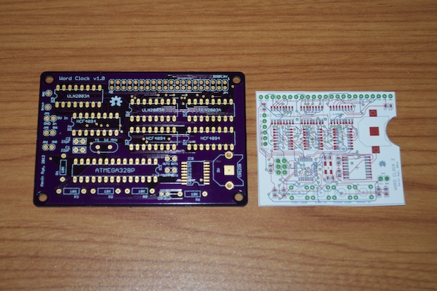
I'll use pogo pins for programming, so I'll also be able to keep the width of the clock super slim by not having to solder on the additional headers. Three boards from OSH Park will only cost $23.15.
The switches and DC jack on version 1 were panel-mount components. They had long leads, long wires, and Dupont connectors that connected to the PCB with 2-pin headers. That’s a lot of unnecessary bulk. It’s one of the main reasons why the clock needed to be housed in such a thick enclosure.
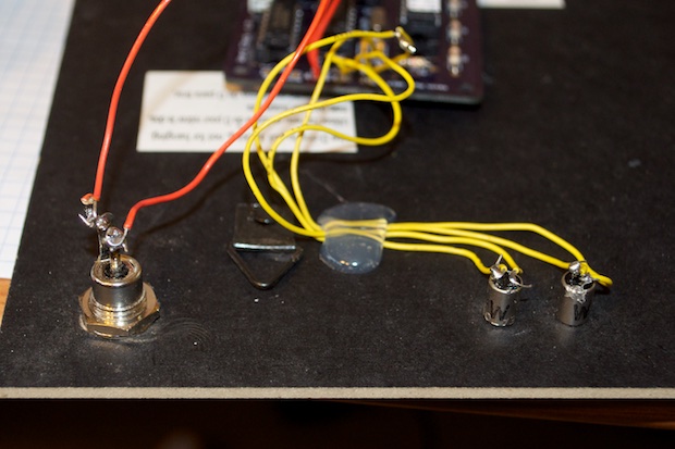
By using mini pushbuttons, I'm hoping to eliminate all that. The buttons will be soldered directly to the PCB and will protrude directly out the back of the enclosure. The enclosure will be 3D-printed and will only be a hair larger than the PCB that it will house.
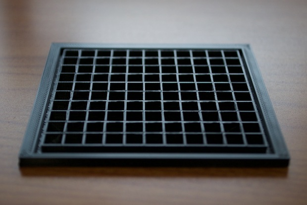
The baffles that shroud the LEDs will also be completely 3D-printed; instead of being cut out of strips of cardboard and held in place with glue.
I took all the coordinates from the silk layer of the PCB and plotted them out in SketchUp.
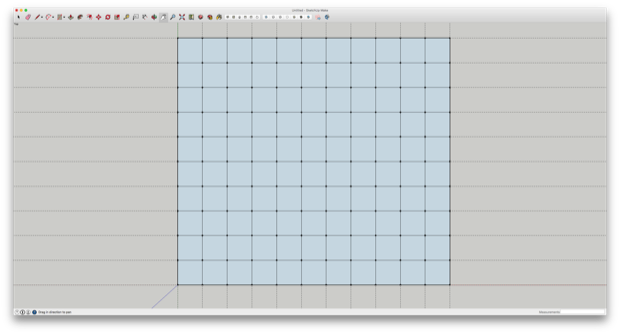
I made the walls 1mm thick and extruded them.
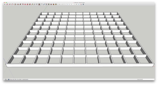
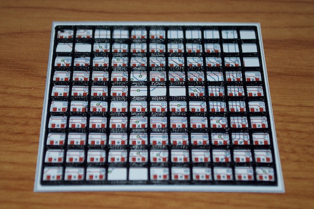
A quick test print, and my proof-of-concept was looking pretty good.
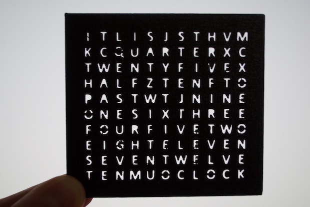
Knowing that I can print baffles small enough for the clock, it was time to try and print a front panel that'll be readable. There's no sense in ordering the PCBs if I can't print a case small enough for it. I suppose I could have a front panel laser-cut, but I'd prefer to 3D print one if I can.
I first tried using 4mm letters, but feared that they'd be too small to be readable.
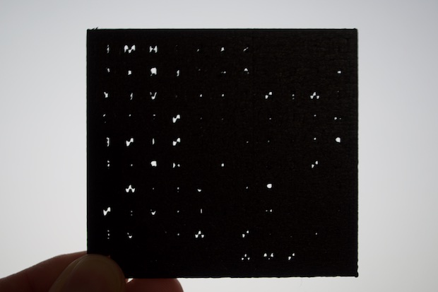
I tried to print the panel with a 2mm thickness. It was unreadable, as I suspected.
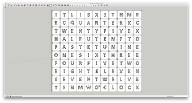
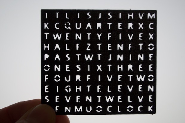
I then tried 6mm letters and made the panel .5mm thick.
Bingo. Making it super thin was the trick. I’ll just need to clean up a few letters with an X-Acto knife and it'll be perfect. After all, the baffles are going to be incorporated into the design, so that'll add the strength and rigidity that it would otherwise be lacking.
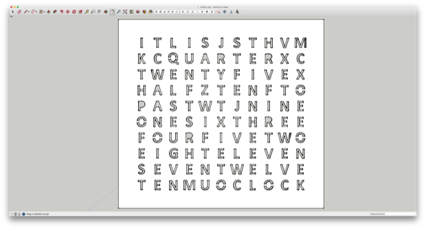
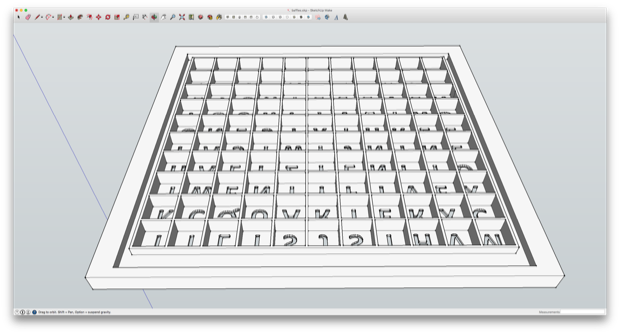
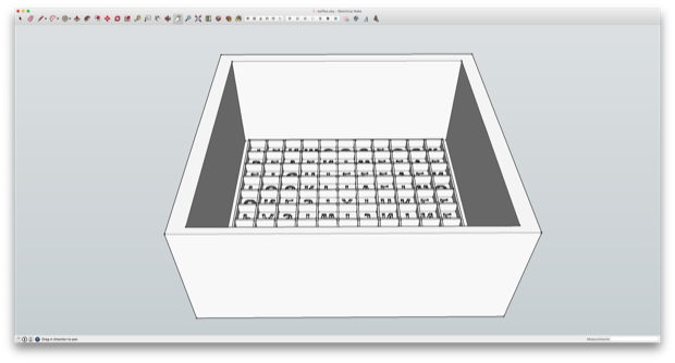
I then completed the panel design by making it a perfect square and incorporated the baffles.
I only made the baffles a few millimeters tall just to see how they’d come out. Keep in mind, I'm still in the proof-of-concept phase, so there’s no sense in wasting time and material.
So far so good. Again, I’ll just need to clean up some letters with a blade, but it looks like this is going to work.
In the final design, the baffles will probably be between 5 and 10 mm tall.
I'll extrude the side walls so that they’ll be tall enough to enclose the PCBs. It’s a little too tall in this example, but you get the idea.
I’ve made the inside dimensions tight enough that the display PCB should slide right in and be held by friction; similar to the way that I secured the
Mini 7-Segment Clock ver 3 in its case.
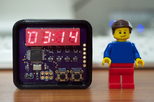
Wow, this thing is going to be tiny when it's done!
With the proof-of-concept nailed, I went ahead and ordered my PCBs. While I waited for the PCBs to arrive, I ordered all the other necessary SMD components. I didn't want this clock to cost me that much more than $100, and with $60 already spent on PCBs, I wasn't looking to spend another $25 on 100 LEDs. (Which is the cheapest I could find them for on DigiKey.) eBay to the rescue. I scored 100 LEDs for $3 bucks.
I just have to wait for the PCBs to arrive, and I can get started on the assembly
See this project from start to finish:
Word Clock 2 - Part I
Word Clock 2 - Part II Word Clock 2 - Part III Word Clock 2 Case Upgrade
