I admit it: I'm a total geek. I love electronics, programming, 3D printing, 3D art, and vintage Apple hardware. I'm always juggling half a dozen projects. I also enjoy documenting it all: my successes, my failures, my experiences... and everything geeky along the way.
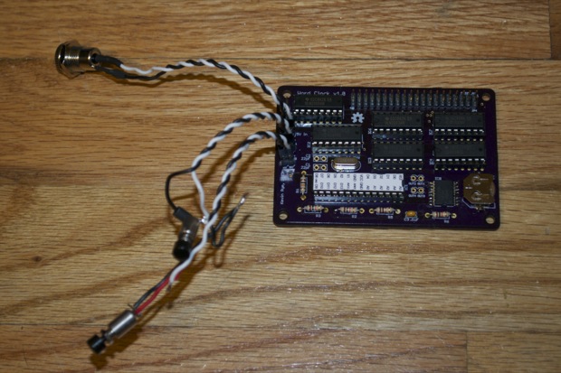
I put together the Word Clock the other day. I went out of my way to make sure that everything was connected together with headers and jumpers.
That way it would be easy to put it together and take it apart if I needed to tinker with it. The problem was, the additional height of the headers made it almost impossible to fit the back on. The extra bulk of those thick wires didn’t help either.
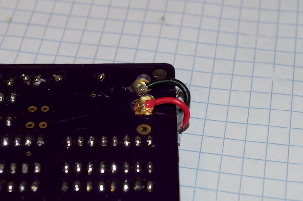
Another problem that I realized was that I goofed again on the PCB. I had the battery on the schematic backwards. So the positive side of the battery was connected to ground and ground was connected to the battery input on the DS3231. That’s not good.
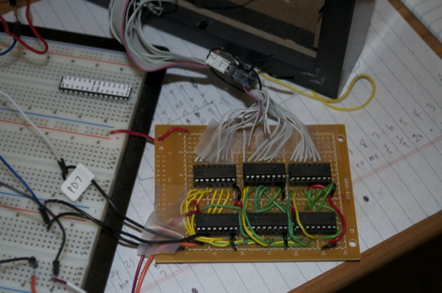
Once I loaded my code, it just didn’t seem to work right. The DS3231 wasn’t doing its thing. It wasn’t holding the time. None of my LEDs were lighting up. Connecting my logic probe revealed that the shift registers weren’t “doing anything”. I thought that backwards battery thing shorted something out. So I threw together a quick fixture to test all the chips.
It works. So I didn’t kill the shift registers. I figured the DS3231 was either causing a short, or I killed it all together. I hastily ripped the chip off the board, but soon found out later that I goofed yet again on the PCB. Instead of connecting the enable pins on the registers to Vcc, I connected them to a digital pin on the ATmega. Oops! All I had to do was enable that pin high in my code and everything worked.
int EnablePin = 9;

pinMode(EnablePin, OUTPUT);

digitalWrite(EnablePin, HIGH);
Anyway, I think I did damage the DS3231 because it never seemed to work after that. I probably could have soldered another one onto the board, but there was still the problem of the battery holder being backwards. I thought about cutting up the board, but it would have been extremely difficult to do it without making a total mess out of it. With two other boards at my disposal, I figured it would be easier (and cleaner) to just assemble another one. As far as the battery, the best solution would be to just run wires to a battery pack of sorts.
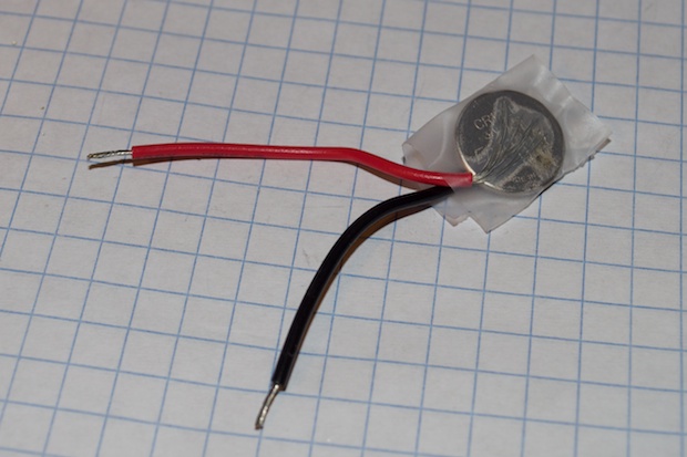
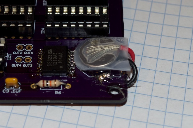
As it turned out, I didn’t have anything that could hold a CR1220 3V battery. I tried to solder leads to one, but that proved to be futile. Not to mention you can seriously damaged a battery by soldering it. The end result? Tape.
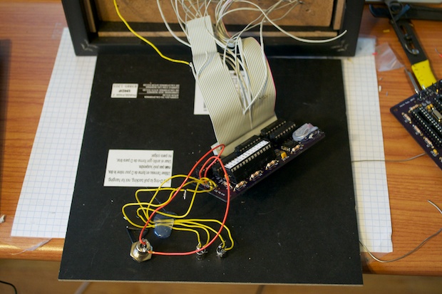
I put together another board and soldered the leads to the battery terminals. I then hot glued them to secure them in place. It’s ugly as sin, but you gotta do what you gotta do. I’m not about to spin another board.
I also put a drop of hot glue under the battery to hold it to the board.
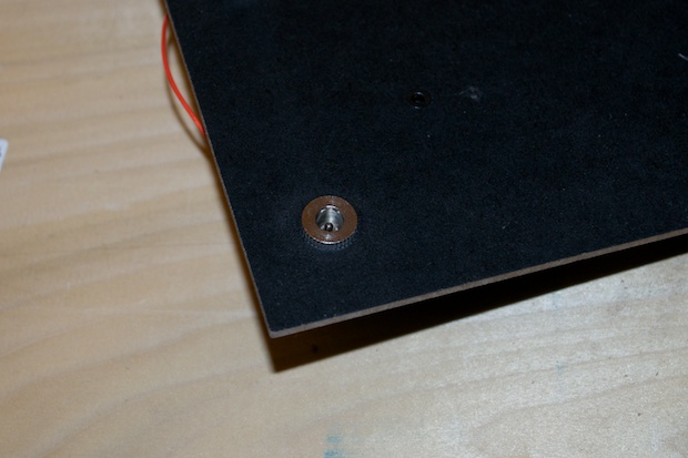
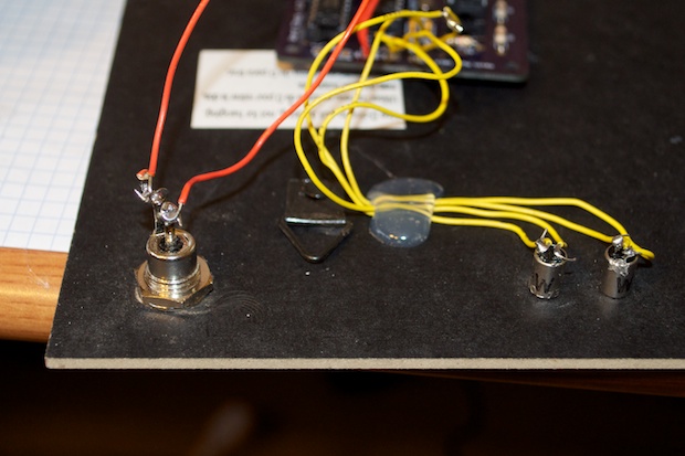
With that out of the way, it was time to finish up the back panel. I drilled a hole for the DC jack.
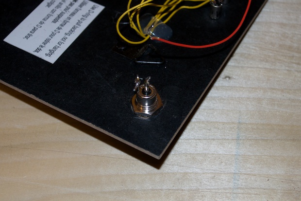
I then wired the rest of it up. I soldered the switches and the jack directly to the board and got rid of those tall headers.
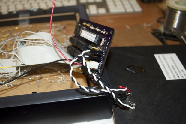
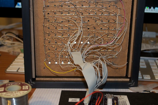
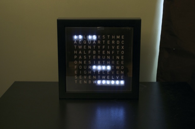
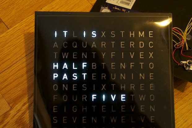
I connected the display and powered it up.
We have lights! It works.
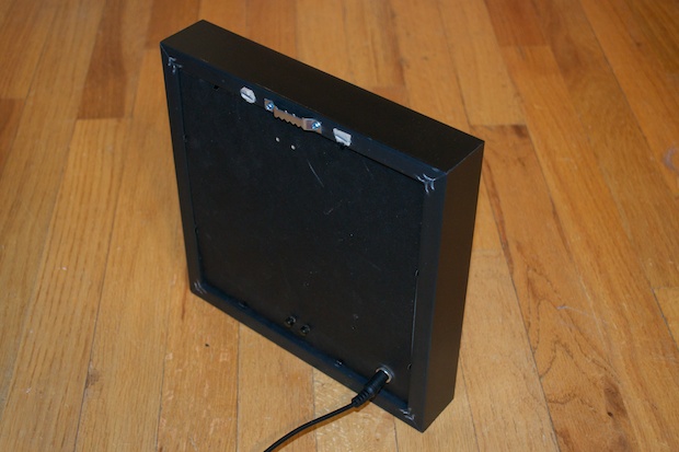
It’s not the best fit, but the cover does go back on better than it did. I still need to do a little work to that. Maybe I’ll glue some standoffs to the back and screw it on. It does’t look bad, but it’s not perfect.
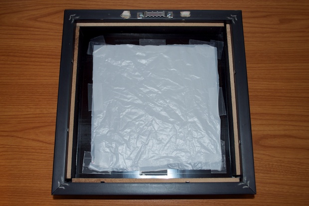
All this tinkering around has wreaked havoc on the display overlay. It’s a mess. I had to tape it on to stop it was falling. I glued a white piece of paper to the back of it, only to tear to off later. I’m not totally happy with the way it looks. You can still see the baffles underneath.
A single piece of paper doesn’t do much to diffuse the light. Two sheets makes it too dim. So some more experimentation is in order. I took my file to Staples and had them print the overlay on their machine.
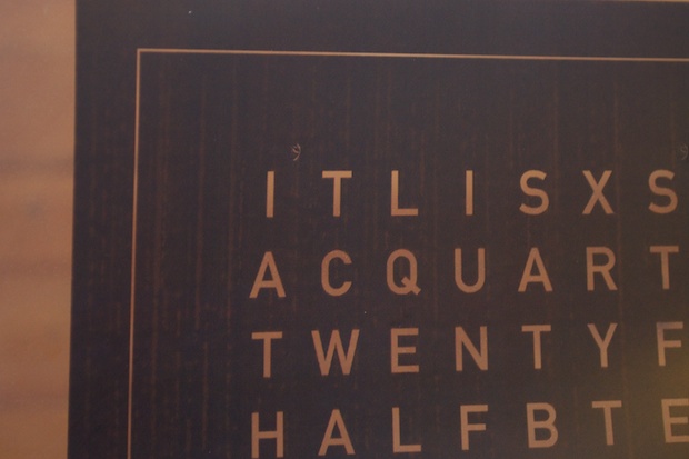
The difference is night and a day. Here’s my overlay printed on my laser printer:
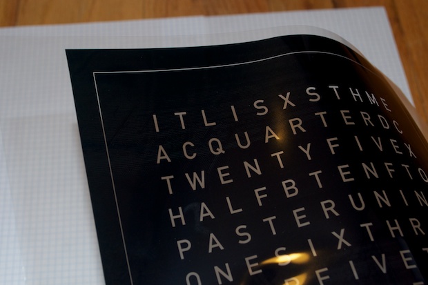
And the one from Staples:
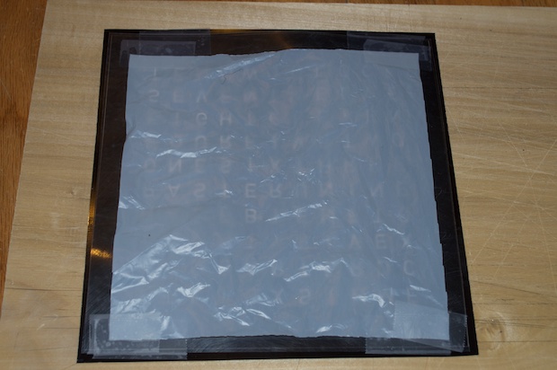
Plain white paper wasn’t exactly doing what I thought it would to diffuse the light, so I cut up a white grocery bag and taped it to the back.
Hey! That looks pretty good!
In the end I decided to tape two layers. I secured the overlay to the inside of the frame and buttoned everything up.