PrototypingOne of the most important things you can do is build prototypes! How mad would you be if you thought that your design was correct and the clock doesn't work. I heard a story of a guy who didn't test his design. He later found out that he had laid out the design not taking into consideration that when you flip the board over to solder the components they are in reverse order. Instead of his clock displaying 12:59.59 it would display 95:95.21. Oops! Talk about starting from scratch!
The prototyping process begins with your initial schematic design. Then you have to try and visualize what the layout will look like. Try and lay it out on paper. Most of the time the components will be placed on the board very differently than shown on the schematic. You need to pick up a project board and some parts. They are great tools for testing your design. You just have to plug in all the components and apply power. Or you can dive right in and design the board and solder all the parts in.
I’ve seen kits that come with a copper board and the etchant solution for about $12. Or you can buy one of the boards that already has traces on it. The kit is great and is very each to use. All you have to do is apply your design to the board using a etchant resistant marker or special tape. Then you dip the board in the solution for about 15 minutes. The etchant eats away all the copper except what is protected by the marker/tape. When the process is finished you wipe down the board with rubbing alcohol to remove the marker/tape. Then you just have to drill all the holes where your components will go. It's that easy!
I purchased most of my parts from Jameco.com along with the board. You'll need a really big board for the final project. I bought a 12" by 12" board and cut it down. The left over piece was used for the bridge circuit. Their prices are great. Also, make sure you get on the mailing list for their catalog.
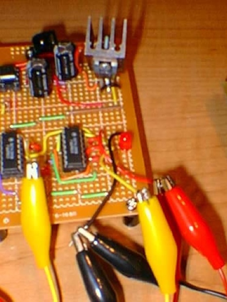
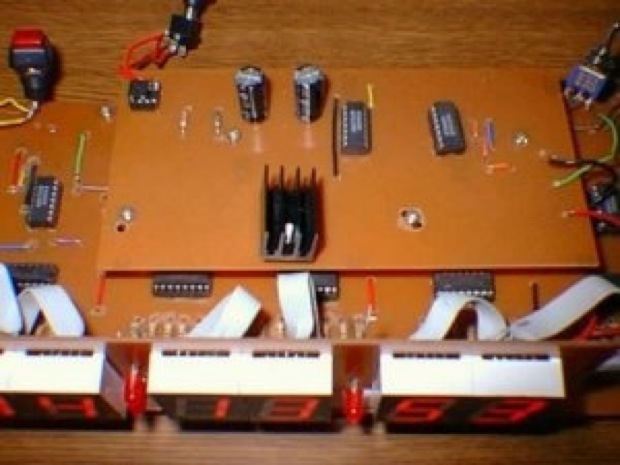
I experimented with various designs and layouts. I even built two separate prototypes for the mins/secs section (after all, they are the same circuit) and the hours section.
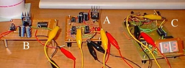
A. Bridge rectifier
B. Counter (divides down 60 Hz to 1Hz)
C. Seconds section
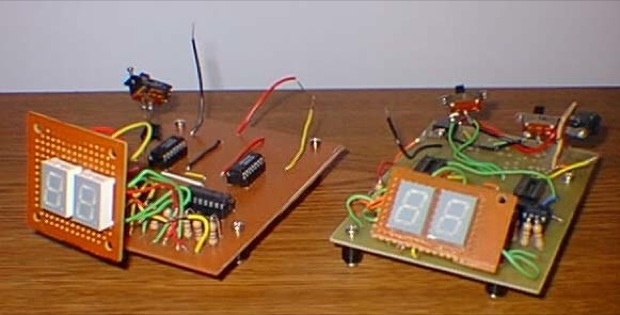
The one on the left was the prototype for the hours. The one on the right is for the min/secs.
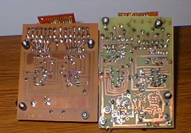
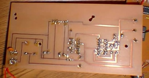
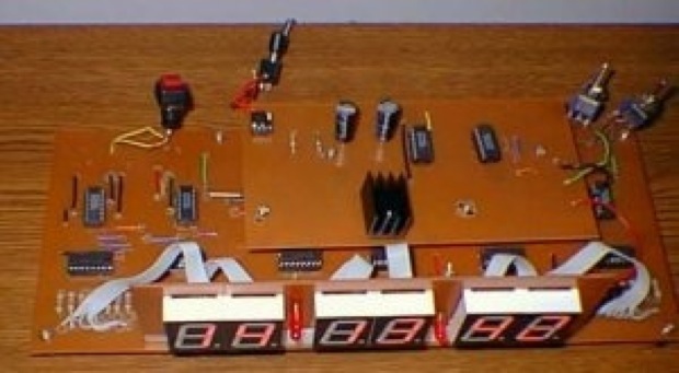
Here you can see the backs. Notice how the one on the right is a very rough draft. You can see on the bottom an unfinished section. I was in the middle of putting in an oscillator using a 555 timer. It was unstable and had a tendency to skip. That was the point in which I decided to go with using a 60 Hz line signal-based input.
I marked the traces on the board with a marker before dipping it in the solution. I stepped up the process on the left prototype. I used tape to mark off the traces. Each piece has to be individually cut and applied to the board before dipping. I looks a lot neater and is more resistant to the etchant solution. If you don't apply the marker thick enough, the solution will eat through the marker causing breaks in the board or weak (thin) traces
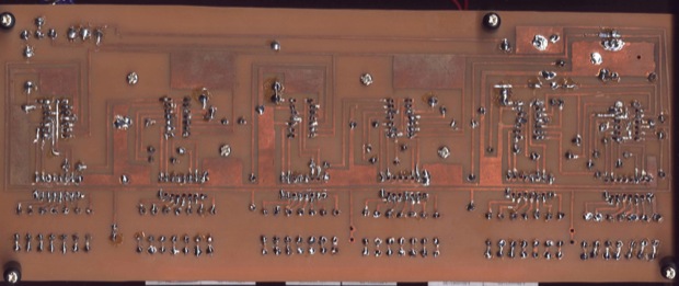
The final version:
 Get your build On - The Parts List
Here’s the list of parts you’ll need to build this clock.
Parts required for the bridge rectifier:
Quantity Part Name
2 7490 Decade Counter
2 14 pin dip sockets for the 7490's 2
2 470µf electrolytic capacitors
1 1K resistor
1 5.1 V Zener diode
1 bridge rectifier (4 pin IC type)
1 4 pin dip socket for the bridge 2
1 9V 450mA AC adapter
1 7805 +5 VDC voltage regulator (T-220 case)
1 Copper-plated project board
4 1" board stands
Parts required for the clock mainboard:
Quantity Part Name
6 7490 Decade Counter *
6 14 pin dip sockets for the 7490's **
6 74247 or 7447 BCD to 7 segment display decoder ***
6 16 pin dip sockets for the 74247's **
6 7 segment display (common cathode)
3 LED's
56 470 resistors ****
1 project board
1 NO (normally open) push button switch
1 2 position toggle switch
1 center toggle switch
2 1N4001 diodes
4 ½" board stands
Additional parts needed:
Part Name
Copper wire.
Rosin-core solder
soldering iron
Rosin
Optional parts needed:
Part Name
logic probe
volt meter
test leads
* you may see 7490's listed as 74LS90. They are the same. You may also use a 5490. It is the military grade chip. It comes in a ceramic package instead of the plastic and has a better temperature rating
** these are optional. However, you may have to order the chips from a catalog or website. You can start your project using the sockets and then put the chips in the sockets later on when they arrive in the mail. That way you won't have to wait to start your project. Also, once those chips are in the board they are almost impossible to take out without messing them up. If you use the sockets, you can take the chips out of the prototype when complete and place them in the final project without wasting them. And the final consideration: if you leave the soldering iron on the chip too long you'll cook it! Soldering the socket is much safer. Cook the sockets as much as you want. Put the chips in last.
*** you may see 74247's listed as 74LS247. They are the same. The only difference between the '47 and the '247 is that the '247 will light up the extra bar on the bottom of the "9" and the top bar of the "6". The '47 will not.
**** You may also use resistor packs. They look like IC's but they have resistors in there. You can use one for each digit. Make sure the ones you use have at least 7 resistors. You will have to modify the board layout to accommodate these.Stage 1 - The Bridge Rectifier
What a Bridge Rectifier does is take the AC voltage from the wall and convert it to DC voltage. This circuit also takes the 60 Hz signal from the AC source and passes it along to the DC output. It then drops the voltage down to 5V via a 7805 voltage regulator. The resulting output will be a 5V DC signal pulsing 60 times a second.
I didn't want this circuit to have to knock down the 120V input signal down to 5V. I didn't want 120V anywhere on this board. Not only is it dangerous, but you also have heat issues to contend with. The AC adaptor I used to power this circuit is an AC to AC adaptor. It does the job of knocking the 120V input signal down to about 12V AC. Most adaptors that you will find are AC to DC adaptors. They are not any good for this application. They do not output a 60 Hz signal.
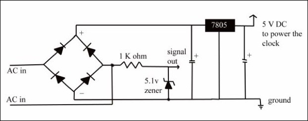
This is a basic bridge rectifier circuit. You will find this in any electronics book. The only addition you might see is the Zener diode. This Zener diode is in there for protection. The diode is reversed biased. In other words, it is "off". It is not conducting.
Below is the initial design laid out on paper, a resulting prototype, and what the final product looked like. It is a good idea to lay the parts down on paper and draw how the traces and connection points should look. This is what you will eventually copy onto your final board.
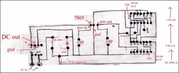
Also mark down on the paper where you will drill the holes. Make sure that the design is feasible and uses the least amount of jumpers.
Your design may change many times. You may be in the final stages of drawing the traces down on the board and realize you need to add something. Maybe another trace or jumper. Sometimes you might do it over because it just looks bad! You can see here that I changed the orientation of the chips on the final version because they were too close together and it made it really hard to solder. I ended up shorting some pins together, what a mess!
I also added 3 connection points on the right for Vcc, ground, and the output signal. A major part of the circuit and I left it out! I also added a cap across the AC inputs on the bottom left. I added this as a last minute alteration to stop some spikes I was getting off the line.
Stage 2 - The Clock
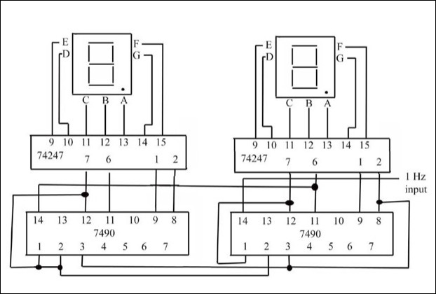
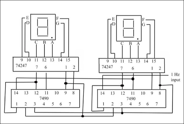
The Seconds and Minutes Section
This is the schematic for the “seconds” section of the clock. The minutes section uses the same circuit. You just have to build 2 of these and link the output on pin 3 from the seconds section to the input on pin 14 on the minutes section. It's that easy. Then you take the output from pin 3 from the minutes section on connect it to pin 14 on the hours.
In essence, you will have 3 separate counting circuits. They are linked together by their input and output pins. Then they all share a line for the setting function. You just have to take the final 3 circuits and lay them out on one board.
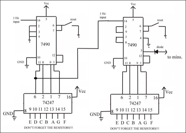
The Hours Section
At some point you need to decide on what format you will be using for your clock, as in 12 or 24 hour mode. The clock I built is in the military 24 hour format. If you choose the 12 hour format you will also have to incorporate an AM/PM light into your schematic. You can do this very easily with a flip/flop
This is the schematic for the 12 hour format:
This is the schematic for the 24 hour format:
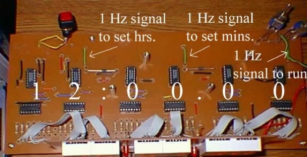
You will also have to incorporate a setting function. Feel free to be as creative as you like with this, as mine is very basic. It would be ideal to have a “fast” and “slow” setting instead of just using the 1 Hz signal to set the clock.
This is the block diagram for the set/run feature.
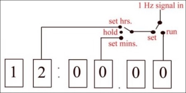
Here is the implementation of the set/run feature as shown on the final board.
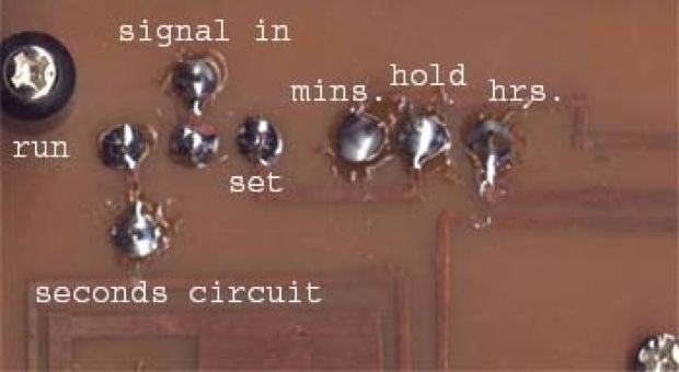
You can see on the final version how the board looks much like the block diagram:
Remember to test your circuit as you build it. Don't wait until you're finished to plug it in. If it doesn't work, where do you begin to troubleshoot? The hardest circuit to troubleshoot is a circuit that never worked! Build it one section at a time.
1.Build the rectifier first. Test it. Make sure it is 5 volts!
2.Build the “seconds” section. Test it. Apply the power and a signal from the bridge. Make sure it counts to :59 and goes back to :00.
3.Build the “minutes” section. Apply power and connect the output from the “seconds” to the input on the “minutes”. Make sure every time the “seconds” reach zero, the “minutes” advance 1 digit.
4.Do the same thing for the hours section.
5.Connect your settings circuit. Test it.
You should have also connected the reset switch to the reset pins. Try that too. Tie all the pins high. Does you clock count? Does it reset when they are low? The 7490 has a reset default of 9 so your clock should look like “99:99:99” when you hit the reset switch.
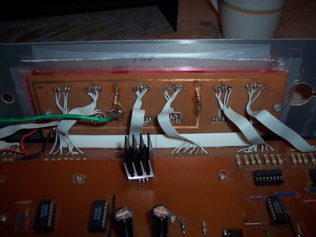
The Final Assembly
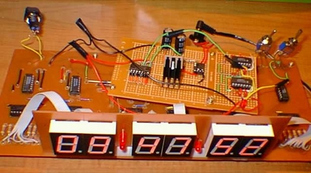
Clock main board with prototype bridge rectifier.
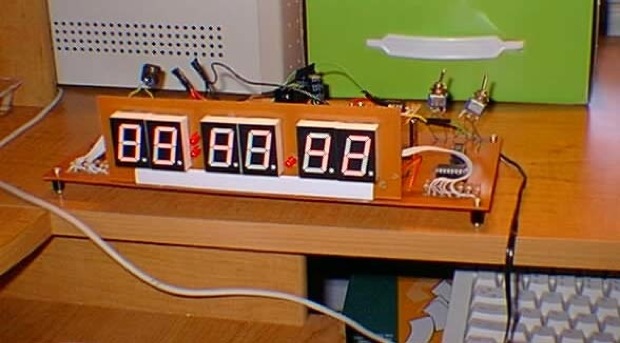
 

Final assembly with final bridge rectifier / timing circuit.

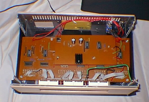
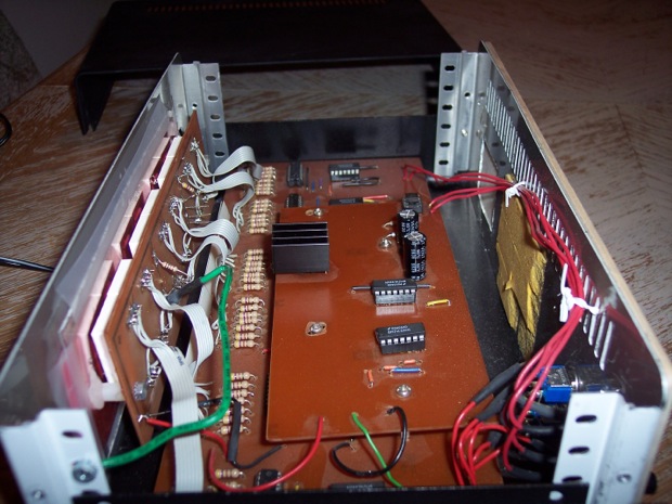
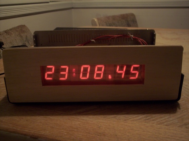
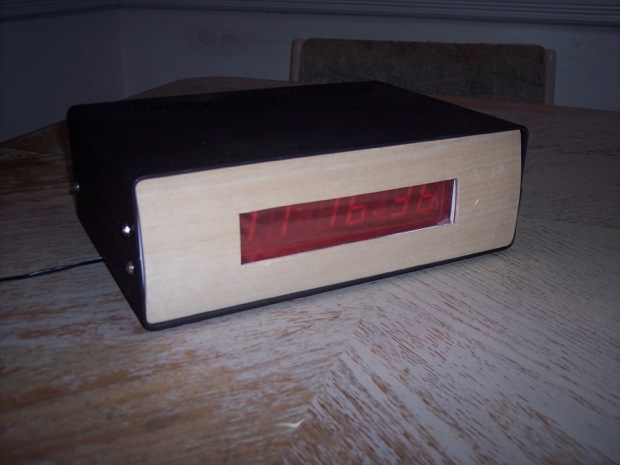
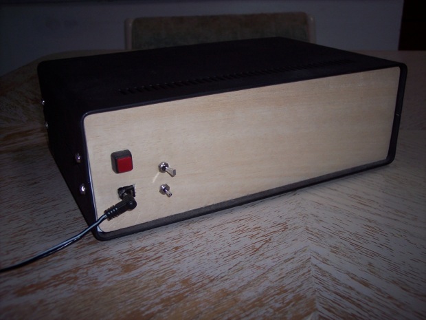
Not the sexiest project box, but it will do.
 See this project from start to finish:
 Digital Clock 1.0
Upgrading My Old 7490 Clock, Part I Upgrading My Old 7490 Clock, Part II Upgrading My Old 7490 Clock, Part III Upgrading My Old 7490 Clock, Part IV Upgrading My Old 7490 Clock, Part V 
