I admit it: I'm a total geek. I love electronics, programming, 3D printing, 3D art, and vintage Apple hardware. I'm always juggling half a dozen projects. I also enjoy documenting it all: my successes, my failures, my experiences... and everything geeky along the way.
Fixing the 7490 Clock, Part III | Kevin Rye.net - Main
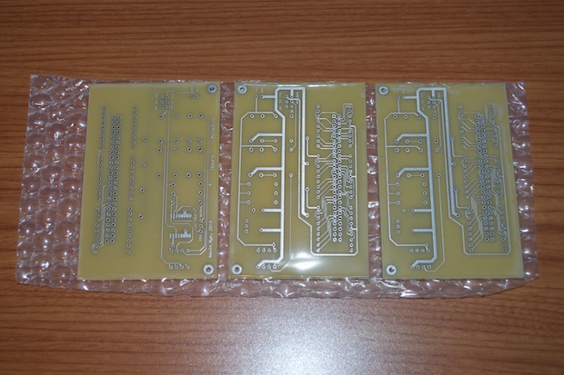
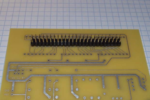
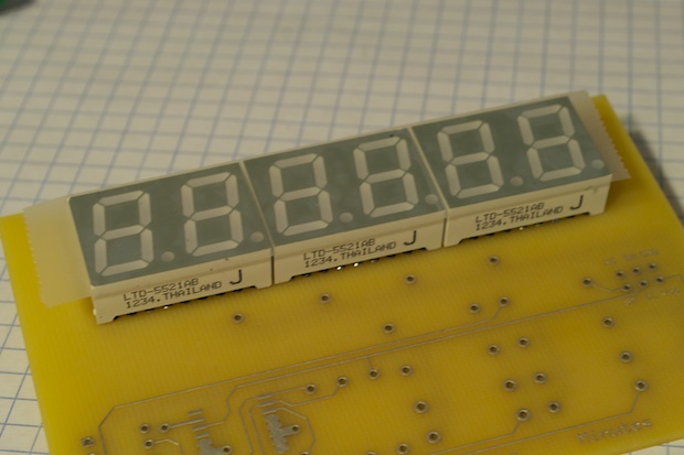
I ordered the boards on a Saturday, and I had them in-hand the following Wed. 
This is what you get with ExpressPCB’s “MiniBoard” service. As long as your board is 2.5” x 3.8”, they’ll make you 3 for $51. If you’re in the “rapid prototyping” phase, it’s great to be able to fire-off a board and have it in hand to use in a few days. They’re not meant to be production boards, so there’s no silkscreen or soldermask.
 
It’s been 5 years since I ordered a board from them. I’m really glad that they haven’t deviated from their process. The board matches the style of the one that I made in 2008.
The whole point of going back and ordering the board from ExpressPCB and using their software was so that the redesigned display board would exactly match the style of the mainboard. If it wasn’t going to, then I would have just designed the new board in Eagle and sent it off to OSH Park. So I’m glad that the two look like they were “made for each other”.
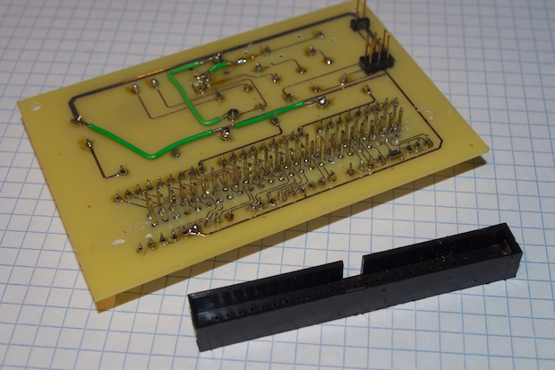
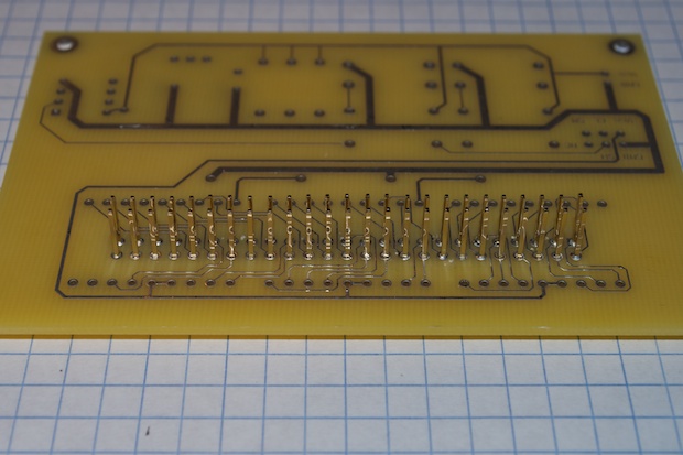
The first order of business was removing the 50 pin header from the back of the old board. I was going to order a new one, but these 50-pin IDC connectors are getting pretty hard to find. Jameco and Digi-Key didn’t have them. Some other sites had them, but only in huge lots. The one or two places that I found that sold them by piece wanted upwards of $5 a pop. That’s crazy! I looked on eBay and you can get them for a dollar or two, but they come from Thailand. I didn’t feel like waiting 2 weeks for a header. So I had to reuse the old one.
Luckily, I was able to just slide a small screwdriver under the edge and lift the shroud right off the pins.
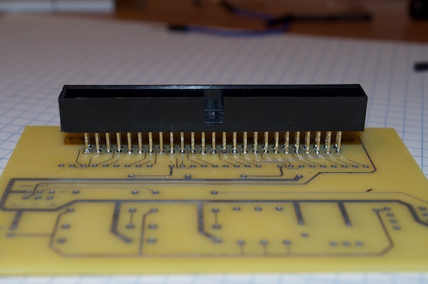
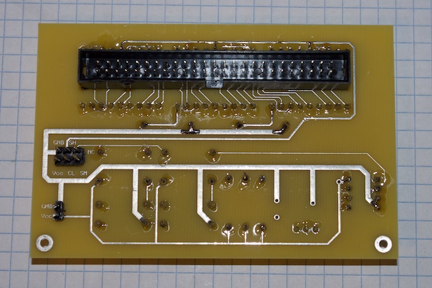
I then soldered in two 25-pin headers that I got from SparkFun.
Once they were in and all nice and even, like before, I slide a small screwdriver under the edge and slid the plastic right off the pins.
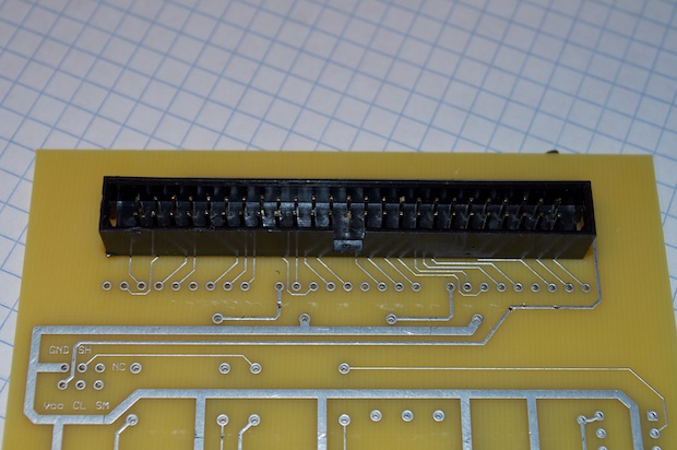
I then slide the old 50-pin shroud onto the pins.
Boom. I just saved myself a bit of money and a ton of time. Did I really need the shroud? No. Does it look really cool and professional? Yes. 
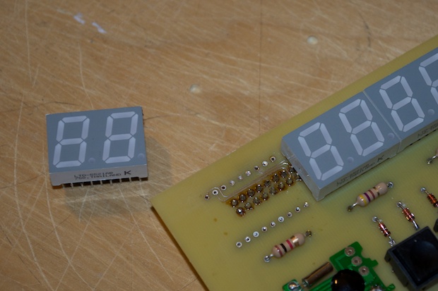
I really didn’t want to have to buy another 3 displays either. Those blue 2x7-segment displays are $8 each. Digi-Key is pretty much the only place that sells them by the piece. I found other sites that sold them for $6-7 bucks, but they had minimum quantities of 500 and 600.
Hot air to the rescue. 
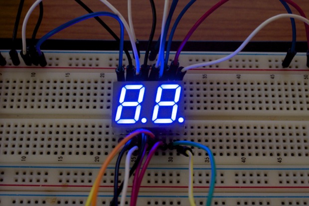
I popped them on my breadboard and powered them up. They survived. Yeh! I saved myself $30 bucks!
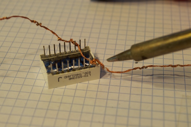
However, they wouldn’t fit into the new board because of all the excess solder on the pins. I needed to clean them up if they were going to fit though the holes. I used some copper braid to remove the excess solder from the pins. 
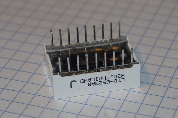
They came out perfect. Look as good as new. 
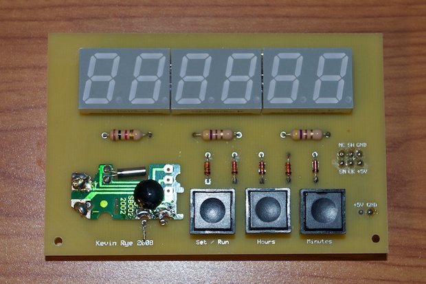
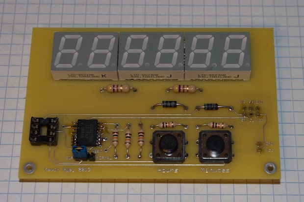
I inserted them into the PCB and covered them with tape so that I don’t scratch them all up when I flip the board over. 
I then soldered them in, along with everything else. 

Lookin’ good!
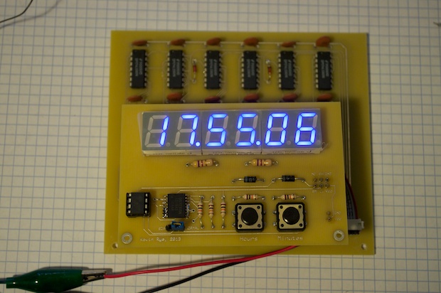
I connected the mainboard to the display board, inserted the ATtiny, and powered it up. Sweet! It works like a charm! I finally nailed it! 
I can’t believe after 5 years, this clock runs like a clock!
All that remains is mounting it in the enclosure.
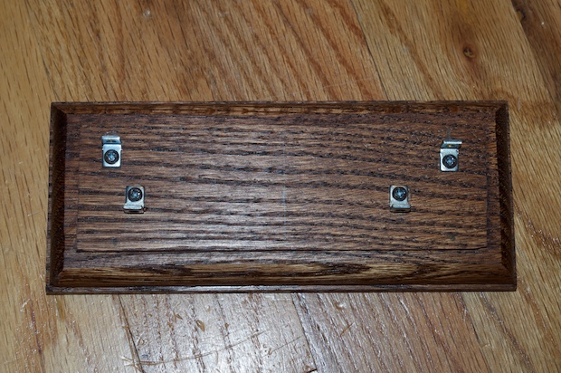
I started by drilling the holes and mounting the hardware that will secure the main and display boards.
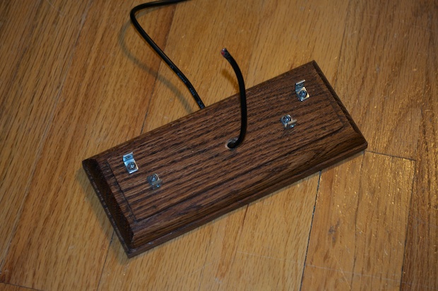
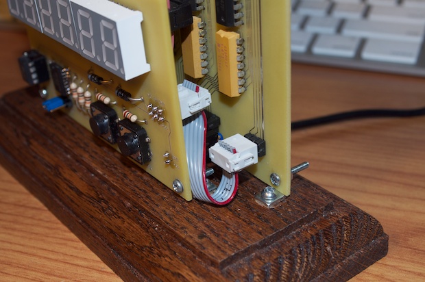
I drilled a hole through the back and on the top until they both met. I then fed the power cord through the hole.
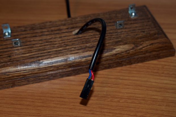
I then soldered on a 2-pin connector. I intentionally left a small portion of the inner wires exposed so I can tell which one is Vcc. The connector isn’t keyed, so I have to go by color.
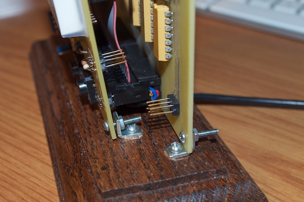
I then attached the two boards and the power connector.
Lastly, I attached the board-to-board ribbon cable.
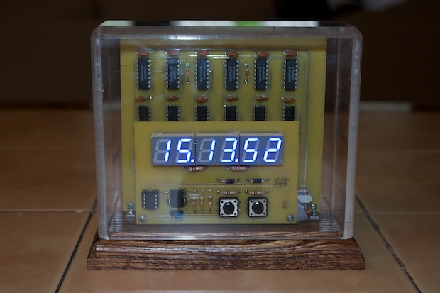
And there it is in all its glory! It’s looks awesome!
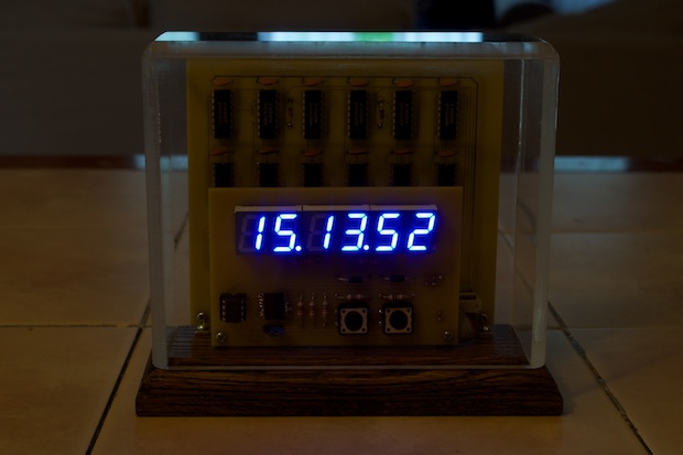
I know the camera doesn’t do the digits justice. They are a really nice looking blue. They look awesome in the dark.
I’m so happy this clock is finally complete and ticking along accurately. It’s been so long. It’s nice to see all this time, money, and hard work finally pay off with such a nice looking clock.