I admit it: I'm a total geek. I love electronics, programming, 3D printing, 3D art, and vintage Apple hardware. I'm always juggling half a dozen projects. I also enjoy documenting it all: my successes, my failures, my experiences... and everything geeky along the way.
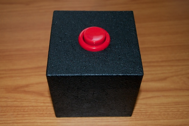
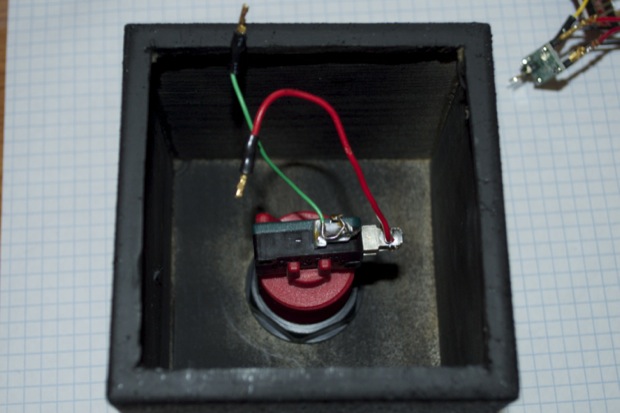
The SoundBox was a fun project. I learned a lot from it. But it’s a one trick pony and a total waste of the $30 worth of tech I ended cramming into that custom enclosure I made.
It would be a shame to waste such a nice looking enclosure. Since I’ve been playing around with the ATtiny, I thought it would be cool to cram it full of RGB LEDs and make a cool rainbow-colored night light for the kids’ room.
I know that the ATtiny, natively anyway, only supports 2 PWM pins. The core can be changed to support 3 PWM pins, but it takes some tweaking to pull it off. I might be able to modulate some RGB LEDS with one. In order to “pulse” RGB LEDs, you need to be able to modulate 3 pins for the red, green, and blue anodes of the LED.
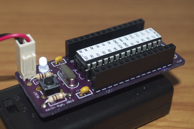
If I can’t pull it off with an ATtiny, I can always use one of my handy-dandy Bare Bones Arduino widgets. Looks like they’re coming in handy already!
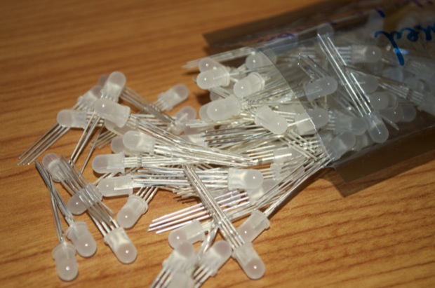
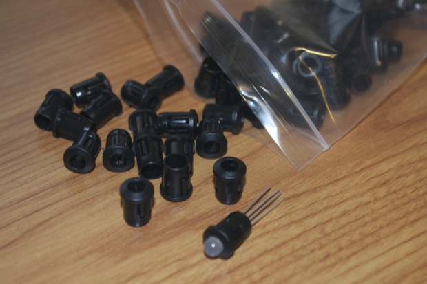
RGBs, relatively speaking, are pretty expensive. Some sites (cough)SparkFun(cough) charge $1.95 for one! Not happening. From my Word Clock build, I know that LEDs can be had for pennies from eBay if you’re willing to wait a week or two for a Hong Kong delivery. I hopped on eBay and secured a bag of 100 for $13.00. I even took the liberty of ordering 100 LED bezels for another $6 bucks. It took exactly 2 weeks for them to arrive. A small price to pay for saving over $200 dollars.
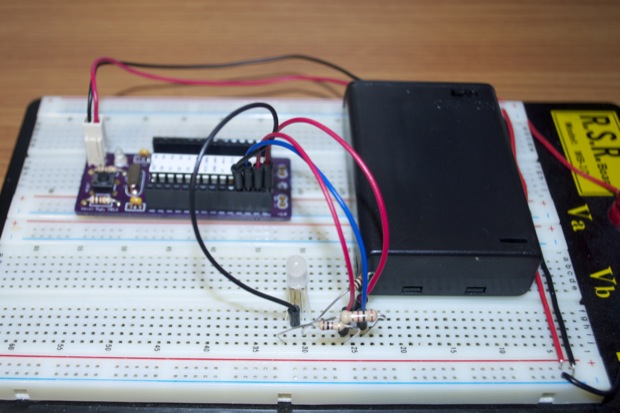
I connected an LED to my Bare Bones widget and then modified the blink sketch to blink each of the red, green and blue anodes.
int red = 6; //red
int green = 7; //green
int blue = 8; //blue

int ground = 5;

void setup() {
  pinMode(red, OUTPUT);
  pinMode(green, OUTPUT);
  pinMode(blue, OUTPUT);
  pinMode(ground, OUTPUT);
}

void loop() {
  digitalWrite(ground, LOW);

  //red
  digitalWrite(red, HIGH);
  delay(500);
  digitalWrite(red, LOW);
  delay(500);

  //green
  digitalWrite(green, HIGH);
  delay(500);
  digitalWrite(green, LOW);
  delay(500);

  //blue
  digitalWrite(blue, HIGH);
  delay(500);
  digitalWrite(blue, LOW);
  delay(500);
}
This should work pretty well as a test fixture for all 100 LEDs. I should be able to run through all of them in no time. I’m sure they all work, but I want to test them all just to make sure I didn’t receive any duds.
I started to dig in a bit and see what I could do with some color blending. I just modified the above sketch to turn on multiple pins at a time. I added a second LED just for fun.
Easy enough. I then started playing around with some PWM stuff to try and blend the colors from one to another. It’s not bad. It needs a little more work. I don’t think the red shows for as longs it should, but it’s a start.
It’s going to look pretty cool when there’s like 20 of these all going off at once!
I already started tinkering with the idea of making a ton of little RGB LED breakout boards for the Night Light. That way, I’ll be able to easy connect a good 20 or so LEDs together inside the enclosure without making a mess with the wiring. Not to mention it’ll be really difficult to solder 60+ resistors to the LEDs without everything falling apart. I can just picture the rats’ nest. Although the SoundBox enclosure is a pretty descent size, the arcade button takes up a lot of space. After I add a battery pack and the Arduino board, there probably won’t be a lot of real estate to work with. So it makes sense to keep everything as small and as tight as possible.
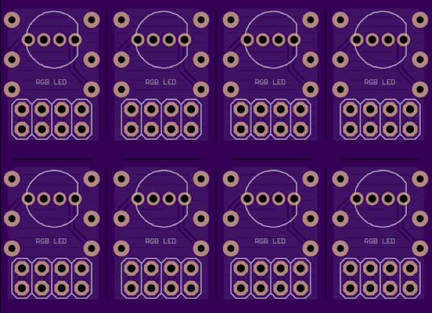
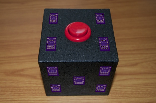
As far as the LEDs, I’m thinking abut putting 5 on each side, and 4 on the top. That’s a total of 24 LEDs. If I squeeze 8 on a PCB, I can get all 24 made with one OSH Park order. I jumped into Eagle and started to put together a board.
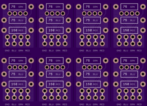
The LEDs will go on one side and the resistors will go on the other. I can then just daisy chain them all together. It should be a very clean build.
I can then cut up the boards and mount them (hot glue) on the inside. I’ll drill holes for the LEDs and finish them with the nice little LED bezels I ordered.
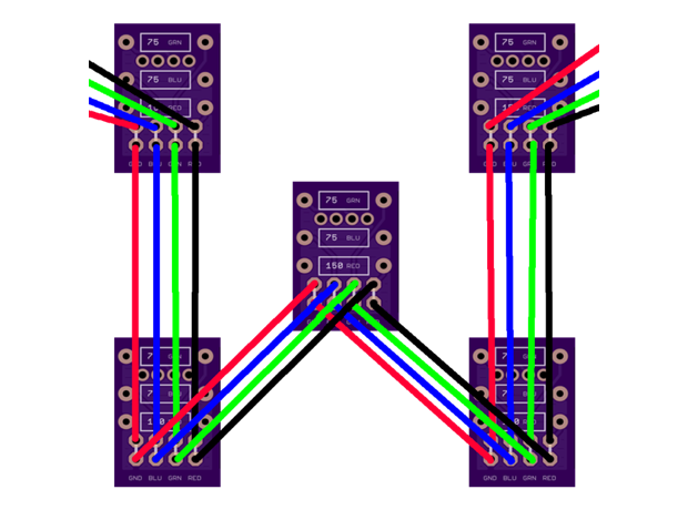
I imagine the wiring for each side will look something like this:
Considering the PCBs from OSH Park are going to cost $17, it looks like this is going to be another “quick and easy” project that ends up costing me $30 bucks. I’m starting to think it’s the enclosure that’s at fault!