I admit it: I'm a total geek. I love electronics, programming, 3D printing, 3D art, and vintage Apple hardware. I'm always juggling half a dozen projects. I also enjoy documenting it all: my successes, my failures, my experiences... and everything geeky along the way.
Since I finished the Word Clock, and I'm waiting for SparkFun to send me a new e-paper display, I figured it was a good time to start playing around with the ATtiny85s that I picked up a few months ago. I placed an order with SparkFun back in December for some hardware to complete my Arduino LCD Clock Stand. I threw them in my order just for kicks. That, and to make the postage worth the $8 bucks I spent on screws and L brackets.
I figured they'd come in handy one day. If you need a quick blinky LED or something, they're nice to have in a pinch. Using up a $6 ATmega328 to blink an LED is a little overkill. ATtiny85s are less than $3 bucks from SparkFun.
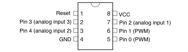
OK, so what exactly can these tiny guys do? They come in an 8-pin DIP package. Vcc and GND are spoken for, so that leaves 6 pins. One pin is for Reset, while the other five are all available for some digital and analog fun.
The great thing about the ATtiny is that you can use the Arduino IDE to program them. They’ll have no trouble running your Arduino code. You are, however, limited to what you can do with them. The ATtiny “only” supports the following commands:
pinMode()
digitalWrite()
digitalRead()
analogRead()
analogWrite()
shiftOut()
pulseIn()
millis()
micros()
delay()
delayMicroseconds()
SoftwareSerial
No extra tools or hardware are required. As long as you have an Arduino board, you’re good to go.
Pins 0 and 1 have PWM (Pulse Width Modulation). That should come in handy for pulsing some LEDs. I’ve read a few posts online where people say all pins are PWM-capable, but I’m not seeing that in the documentation. So I’ll just have to try it.
So how do you program these bad boys? There’s definitely no shortage of instructions online on how to do this. So I’ll point you a good read and show you what I did.
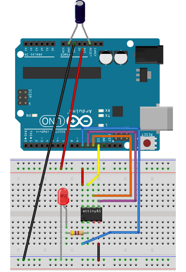
Basically, you can configure your Arduino as an ISP and it’ll program the ATtiny for you. Download the additional support files from High-Low Tech and place them in your Arduino folder.
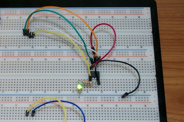
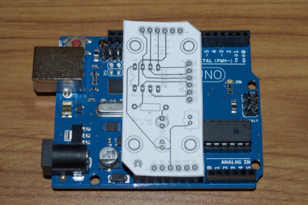
You have to connect the ATtiny to your Arduino board like this (LED optional):
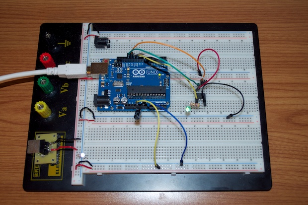
Which should look something like this in the real world:
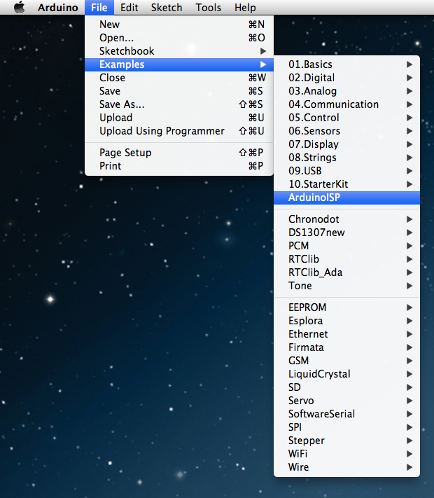
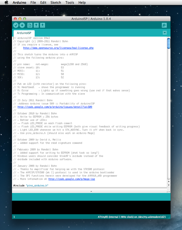
Launch your Arduino IDE. Select “File” > “Examples” > “ArduinoISP”.
That will open the “ArduinoISP” sketch.
You’ve probably already been sketching away, so leave the IDE set up to talk to your Arduino board like you normally would.
Upload the “ArduinoISP” sketch to your board.
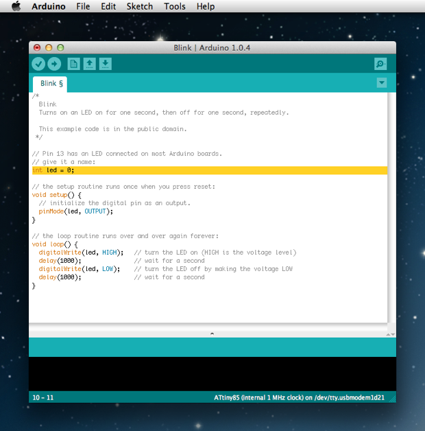
Once the upload is complete, open the example “Blink” sketch and change pin 13 to a pin on your ATtiny. I changed mine to pin 0.
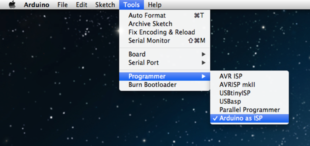
Go to “Tools” > “Programmer” and select “Arduino as ISP”.
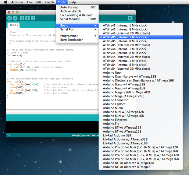
Then go to “Tools” > “Board” and select your ATtiny. Since I’m not using an external crystal, I selected the internal 1MHz option.
Then go ahead and upload the sketch. Your Arduino will program the ATtiny with the Blink sketch. If all goes well, you’ll see the LED blink on and off. Don’t worry if you see some errors about PAGEL and BS2. That’s normal.
Success!
Once the ATtiny has been programmed, you can remove the Arduino and it’ll happily tick along on its own.
Another video of it in action, solo mode:
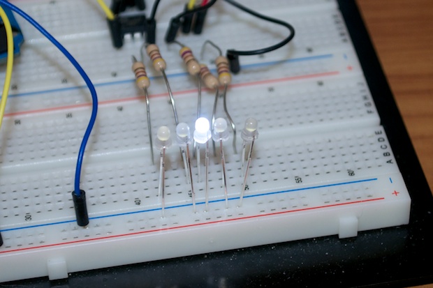
This is pretty easy. With the logistics out of the way, it was time to start playing around. I wanted to try every pin, so I connected an LED to pins 0, 1, 2, 3, and 4 and then loaded the following sketch:
I also wanted to see how many pins really have PWM. So I loaded the following sketch just to see:
int led0 = 0;
int led1 = 1;
int led2 = 2;
int led3 = 3;
int led4 = 4;

void setup() {
  pinMode(led0, OUTPUT);
  pinMode(led1, OUTPUT);
  pinMode(led2, OUTPUT);
  pinMode(led3, OUTPUT);
  pinMode(led4, OUTPUT);
}

void loop() {
  // fade in from min to max in increments of 1:
  for(int fadeValue = 0 ; fadeValue <= 255; fadeValue +=5) {
    // sets the value (range from 0 to 255):
    analogWrite(led4, fadeValue);
    analogWrite(led3, fadeValue);
    analogWrite(led2, fadeValue);
    analogWrite(led1, fadeValue);
    analogWrite(led0, fadeValue);
    // wait for 30 milliseconds to see the dimming effect
    delay(50);
  }

  // fade out from max to min in increments of 1:
  for(int fadeValue = 255 ; fadeValue >= 0; fadeValue -=5) {
    // sets the value (range from 0 to 255):
    analogWrite(led4, fadeValue);
    analogWrite(led3, fadeValue);
    analogWrite(led2, fadeValue);
    analogWrite(led1, fadeValue);
    analogWrite(led0, fadeValue);
    // wait for 30 milliseconds to see the dimming effect
    delay(50);
  }
  delay(1000);
}
No such luck. Just like the documentation says, only pins 0 and 1 have PWM. The LEDs on pins 0 and 1 “breathe”, but the rest of the LEDs just go on and off.
With that question answered, it was time to dig in and see exactly what I can do with these. I’ve seen several examples of people making LEDs “breathe” just like the LEDs on MacBooks. It’s a really nice effect. I’m thinking that the enclosure I made for the SoundBox would benefit from having a lot of “breathing” LEDs on it. Maybe it would make for a nice night light for my kids’ room. That penguin is only going to last for so long!
I started to play around with the code and came up with some pretty nice results. With a little more time I’m sure I could have nailed it, but after a quick Google search I found this sketch over at The Custom Geek that’s exactly what I’m looking for. Well done!
int led = 0;
int i = 0;

void setup() { // bring the LED up nicely from being off
  pinMode(led, OUTPUT);

  for(i = 0 ; i <= 15; i+=1)   {
    analogWrite(led, i);
    delay(5);
  }
}

void loop() {
  for(i = 15 ; i <= 255; i+=1)
  {
    analogWrite(led, i);
    if (i > 150) {
      delay(4);
    }
    if ((i > 125) && (i < 151)) {
      delay(5);
    }
    if (( i > 100) && (i < 126)) {
      delay(7);
    }
    if (( i > 75) && (i < 101)) {
      delay(10);
    }
    if (( i > 50) && (i < 76)) {
      delay(14);
    }
    if (( i > 25) && (i < 51)) {
      delay(18);
    }
    if (( i > 1) && (i < 26)) {
      delay(19);
    }
  }
  for(i = 255; i >=15; i-=1)   {
    analogWrite(led, i);
    if (i > 150) {
      delay(4);
    }
    if ((i > 125) && (i < 151)) {
      delay(5);
    }
    if (( i > 100) && (i < 126)) {
      delay(7);
    }
    if (( i > 75) && (i < 101)) {
      delay(10);
    }
    if (( i > 50) && (i < 76)) {
      delay(14);
    }
    if (( i > 25) && (i < 51)) {
      delay(18);
    }
    if (( i > 1) && (i < 26)) {
      delay(19);
    }
  }
  delay(970);
}
Here’s a video of it in action:
One LED looks cool, but what about 6?
The results are pretty nice. The camera shows a flicker when the voltage ramps up and down, but it’s the speed of the camera. (I switched from my iPhone to my Nikon.) In reality it’s actually nice and smooth.
I can’t get over how bright these LEDs are! I know the video and pictures don’t do them justice, but they actually hurt to look at. That’s why I used 1K resistors in my Word Clock. The usual 330-470 Ohm range just doesn’t cut it.
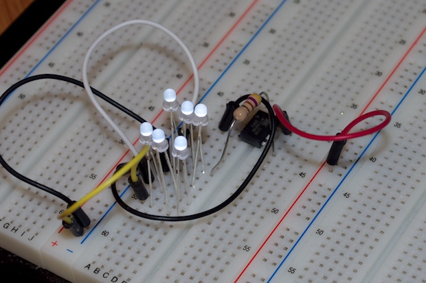
I covered it with a plastic tub that I had lying around to help diffuse the light. A couple of RGB LEDs cycling through the rainbow would probably look really cool at night.
I wonder how many LEDs I can drive with both pins before I break it? Funny, but I’ll leave that for another day.
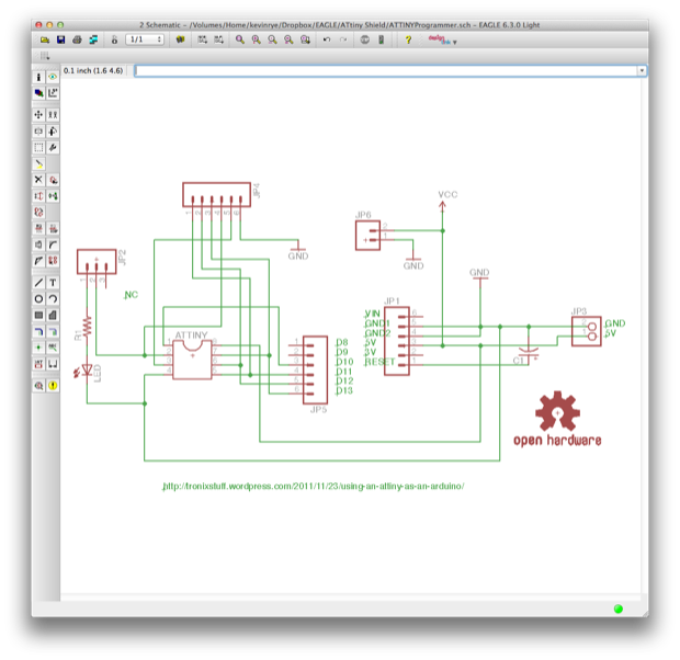
This is all well and good, but it would be so much easier to program the ATtiny without having to breadboard it every time. It would be really cool if I had a shield I could just pop one in to. SparkFun sells a USB programmer that fits the bill, but it’s $20 bucks. It looks really cool, but this is such a simple thing to set up, it should be very easy to make a shield for it. I pondered it for a bit and thought that it would be really cool if the shield also doubled as the PCB for the final project. I could make a shield for the ATtiny and just break out the pins and add an additional connection for power. After I’d programmed it, I could hook anything up to it that I wanted, connect a battery pack, and it would run on its own. It’ll be really small too, so having boards made should only cost a few bucks.
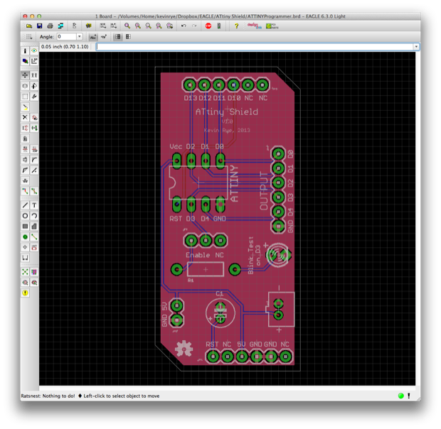
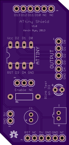
I jumped into Eagle and laid out a schematic. There’s headers that line up with my Arduino board as well as headers for external connections and power. I even threw an LED on the board so I can run the Blink sketch to make sure everything works “out-of-the-box”.
The board looks pretty cool. It’s tiny!
Having 3 boards made by OSHPark would only cost me $10.50.
I played around with having some holes for boards stands, so that I can mount it in a project box if need be, but it’s probably overkill. Whatever I make with these will probably hold together with a drop of hot glue
That’s way cheaper than SparkFun’s $20 programmer and it’ll also double as the PCB for a finished project. Even with the rest of the components (8-pin DIP, headers, etc.) a completed board would only cost me $10. That’s not bad for a cool pulsing night light!