I admit it: I'm a total geek. I love electronics, programming, 3D printing, 3D art, and vintage Apple hardware. I'm always juggling half a dozen projects. I also enjoy documenting it all: my successes, my failures, my experiences... and everything geeky along the way.
GPS Clock Prototyping, Part II | Kevin Rye.net - Main
It’s been a few months since I worked on the GPS clock. I couldn’t nail down exactly how I wanted it to work. I had a few ideas floating around, as well as a list of what features I wanted to include. However, in order to build the clock without compromises, I would have to overcome several hurdles. Considering I was already juggling a few other projects, I figured it was best to shelf it until I had a clearer vision of exactly how I wanted it to work and how I’d pull it off.
The original plan was the stream the time from a GPS module, but when I actually saw it in action, it became clear that it wasn’t the way to go. The problem lies in the fact that the time on the GPS model doesn’t run locally. I thought maybe the GPS model had an internal RTC that synced with a GPS satellite and that once it pulled the time down, it was free to run on its own. That’s not the case. As soon as you lose the link, the clock stops. Ideally, I’d like the clock to run even if it can’t get a link. It seems unrealistic that I’d be able to link to a satellite 24-7, so I don’t want to clock to have to rely on a GPS signal in order to function. In addition, who knows how the technology will change down the road? Will there even be a satellite to connect to? Will this GPS model even work in 10 years?
Basically, I want the ability to sync with a GPS satellite to serve as a means to update the clock with the most accurate timebase possible, then run on its own until such a time as I deem it should re-sync with a satellite for a time update. Maybe once a day pull in the time from the GPS satellite, then run locally with a DS3231 RTC. The DS3231 in itself is an extremely accurate RTC. The first digital clock I built has been sitting on my desk for a year and it’s still to-the-minute. I agree that syncing the time with a GPS satellite to keep it accurate is total overkill, but I want to do it anyway!
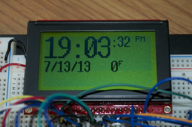
When I last left it, I had somewhat of a GUI with the time, date, and temperature being displayed.
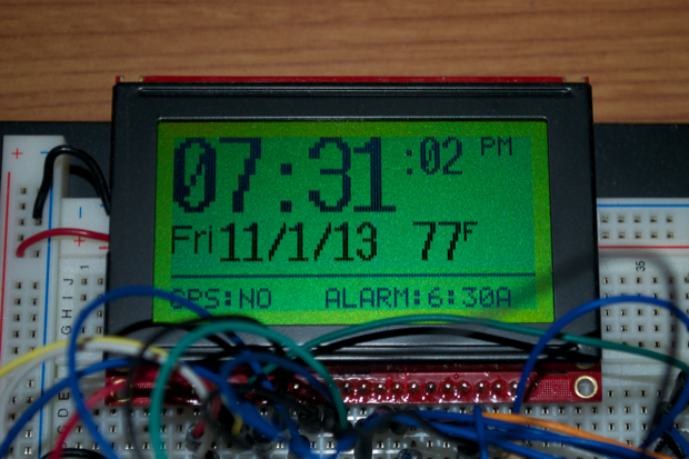
I also want to add an alarm function and some way to denote that the alarm is set. I played around with the idea of having a bell icon display when the alarm was set, but I ditched that idea after I had implemented it. With so much screen real estate at my disposable, I though it would be a better idea to actually display the time the alarm is going to go off. I also though since I’m only going to sync with a GPS satellite once a day, I could put a “Date of last sync: xxxx” on the display.
With that, I added a line on the display to sort of separate the display into two “zones”. I added a GPS and ALARM area to the bottom. I just hard-coded the data there so I’d know how much space I had to play with.
As far as a settings menu, I put in a single button in order to bring up the menu.
This is what really hung me up. The whole point of making it a GPS clock would be so that I would’t have to set the time. If I don’t have to set the time, I shouldn’t need any buttons. I wanted the clock to be no bigger than the LCD itself. I wanted it so that as soon as you turned it on, it just set itself and ran happily on it’s own with zero intervention from the user.
Hummm, but without buttons...how would I set the alarm? The more I thought about it, the more I realized I needed buttons. I’d need a button to bring up the settings menu. I’d need up and down buttons to navigate to each field. I’d need buttons to change the fields. I’d need a button to cancel/silence the alarm. Buttons! Buttons! Buttons!
I DON’T WANT ANY BUTTONS!!!!!
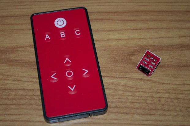
After kicking a few ideas around, I came up with the idea of making it remote controlled! I ordered an IR remote and an IR receiver from SparkFun. I couldn’t move forward with the code until I had the parts in hand. So it was around that time that I shelved it.
I’ve had the parts for a few months now, so it’s time to get back into it.
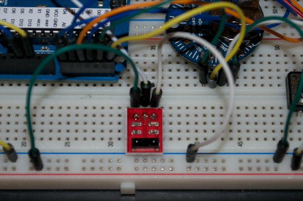
I soldered a header onto the IR receiver and added it to my breadboard.
SparkFun provides a quick and easy example sketch to show you exactly how to pull the codes from the remote. The sketch is based off Ken Shirriff's code found on GitHub, so you’ll need to download his library.
#include <IRremote.h>

int RECV_PIN = 12;
IRrecv irrecv(RECV_PIN);
decode_results results;
#define POWER 0x10EFD827
#define A 0x10EFF807
#define B 0x10EF7887
#define C 0x10EF58A7
#define UP 0x10EFA05F
#define DOWN 0x10EF00FF
#define LEFT 0x10EF10EF
#define RIGHT 0x10EF807F
#define SELECT 0x10EF20DF

void setup() {
  Serial.begin(9600);
  irrecv.enableIRIn(); // Start the receiver
}

void loop() {
  if (irrecv.decode(&results))
  {
    if (results.value == POWER)
    {
      Serial.println("POWER");
    }
    if (results.value == A)
    {
      Serial.println("A");
    }
    if (results.value == B)
    {
      Serial.println("B");
    }
    if (results.value == C)
    {
      Serial.println("C");
    }
    if (results.value == UP)
    {
      Serial.println("UP");
    }
    if (results.value == DOWN)
    {
      Serial.println("DOWN");
    }
    if (results.value == LEFT)
    {
      Serial.println("LEFT");
    }
    if (results.value == RIGHT)
    {
      Serial.println("RIGHT");
    }
    if (results.value == SELECT)
    {
      Serial.println("SELECT");
    }
    irrecv.resume();
  }
}
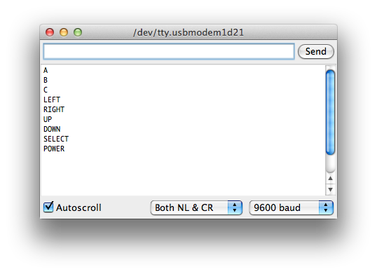
It works! Each subsequent press of a button is displayed in the serial monitor. Knowing how it worked, I redid the code so that the “A” button toggles between the main screen and the Settings menu.
Here’s a 5 second video to show it in action:
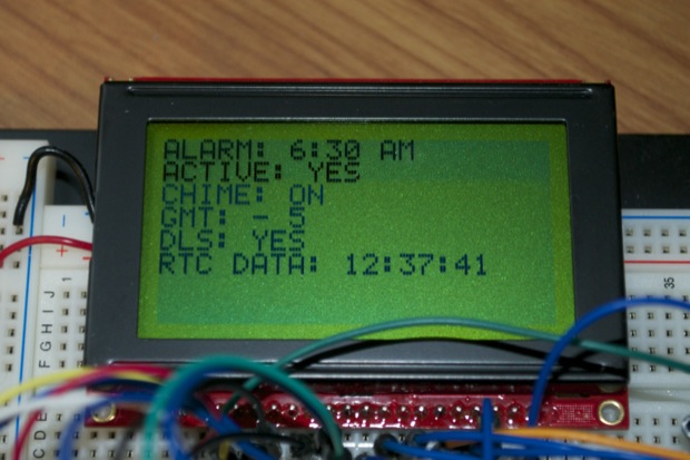
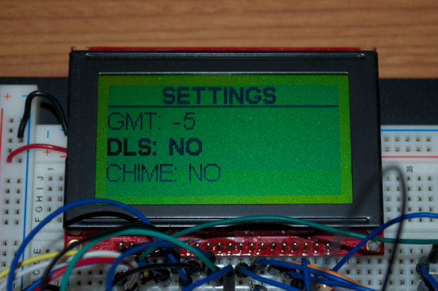
With the remote figured out, it was then time to fully implement the Settings menu. Not only do I need to bring up the menu with the remote, but I need to be able to step through each field in the menu and change the values. I redid the menu so that it looked a little nicer.
That looks OK, but rather than cram everything into the one menu, I decided to break the general settings and alarm functions into two separate menus.
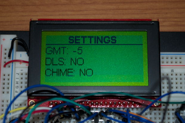
Button “B” will bring up the Settings menu. From there I’ll be able to set the time zone, daylight savings, and chime on the hour.
Pressing the up/down arrows advances to the next/previous entry. I haven’t implemented the left/right arrows yet, but they’ll advance/toggle the values.
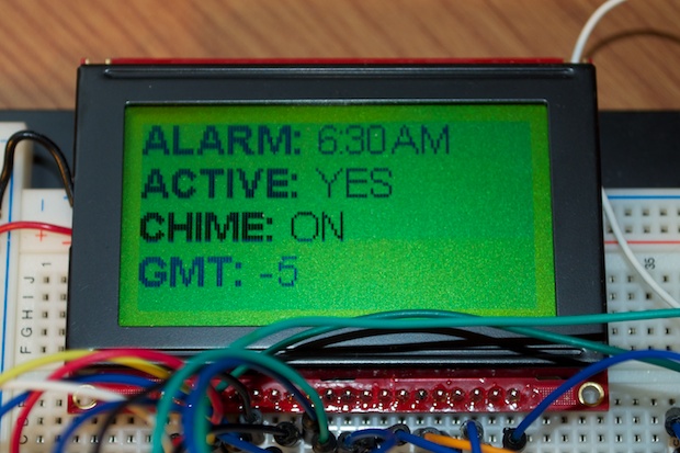
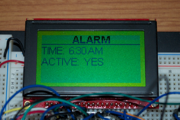
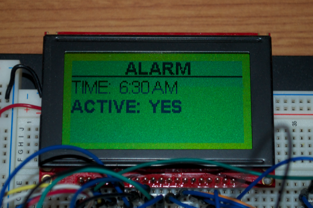
Button “C” will bring up the Alarm menu. From there I’ll be able to set the alarm time and active/deactivate the alarm. I might put in a snooze function too, but we’ll see.
Again, the up/down buttons step through the fields, and once implemented, the left/right buttons will advance/toggle the values. I’ll also have to make the hours, minutes, and AM/PM designation separately-selectable fields.
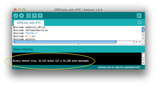
So why haven’t I fully implemented the left/right arrows? This is why:
The ATmega328 has 32K of memory. I’ve already used 31.4K. Yup, I just ran out of programming space, and the code’s not even half finished! Maybe I could find some fancy ways to streamline the code. Maybe I could abbreviate all my variables to smaller names. But realistically, how much memory am I actually going to pull back? 1K? Maybe if I was lucky. It’s not so much my code that’s taking up the space, it’s all the libraries I’ve linked to.
I’ve linked to Adafruit’s GPS library, the SoftwareSerial library, the DS3231 library, the Wire library, the GLCD library, the IR Remote library, as well as 6 font libraries. That’s where all the memory went. There’s no getting around it. Sure, I could probably dig into the header files and pull out all the functions that I’Il never call, but is it worth it? For the most part, those libraries are all pretty clean. I could tweak them until the cows come home, but something tells me that I won’t even come close to recovering the amount of code space that I’ll need to implement all the features that I want.
It’s not just a matter of pulling back a few K to throw in a minor little “nice to have”. I haven’t fully implemented the basic functionally of the Settings an Alarm menus. I still need to write all the code that pulls the time in from the GPS module, writes it out to the RTC, and then has the LCD display the time from the RTC. I also need to write all the code to save all the settings in the EEPROM, and read it all back in at power up. Lastly, I need to add all the code for the alarm, as well as provide some kind of audio tone and/or audio file.
Bottom line, I need more memory than the ATmega328 can provide. I don’t like to compromise. Once I have a clear vision of how something needs to be, it needs to be that way.
Solution? Upgrade!
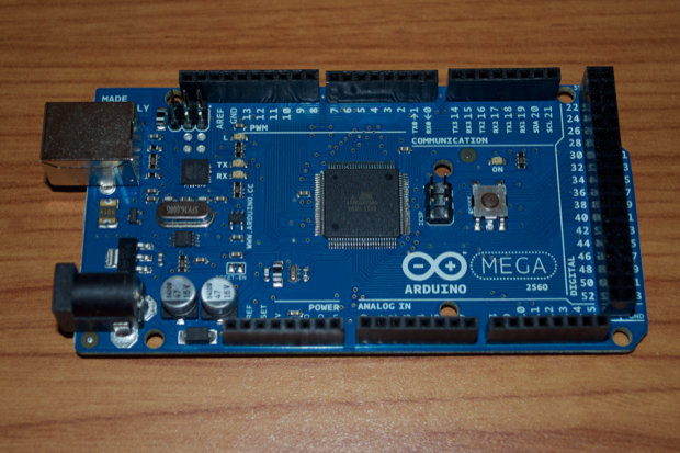
Ladies and gentlemen, I give you.... the Arduino Mega 2560!
The ATmega2560 has 256K of memory and 8K of RAM. That’s 8 times the programming space and 4 times the RAM! Not to mention it also has 16 analog inputs and 54 digital I/O pins. That’s 48 more than the Uno. Insane! This guy should have memory and I/O to spare!
I just hope when the time comes to assemble the PCB, I can solder a 100-pin SMD chip with a 0.8mm pin pitch! After all, they’re $17 bucks a pop! At that price, you want to get it right the first time.