I was amazed at how fast my GPS PCBs arrived in the mail. Usually OSH Park takes a good 2 weeks to turn around a board. However, this time they arrived in 5 days. There is a catch. There was a little slip of paper inside my envelope that said they were testing out a new super-fast order option. They said in the future, the rush service will be an additional $90 bucks! I definitely like having my PCBs turned around in 5 days, but not at that price.
In any case, the boards look great...and they arrived just in time for the weekend!
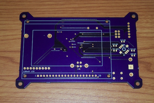
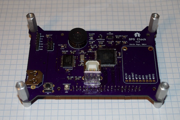
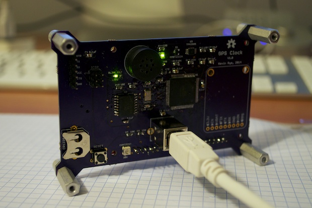
This is probably the largest, and most complicated board I’ve designed so far.
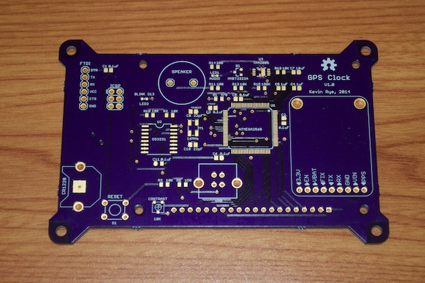
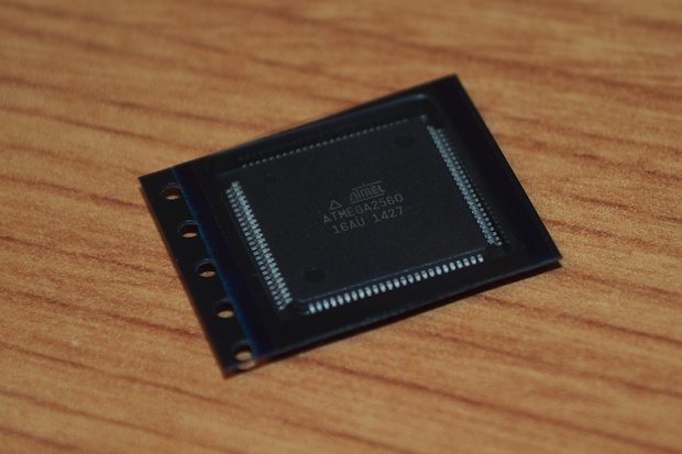
Not only does this board have a ton of stuff going on (RTC, GPS, 128x64 LCD, FTDI) but it also uses a 100-pin ATmega2560. A royal pain to solder by hand; even with the drag-soldering technique. One wrong move, and it’s $18 bucks down the drain.
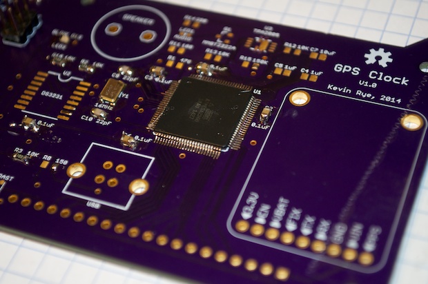
To start out, I soldered in the ATmega and the supporting components. There’s no sense in soldering everything in all at once to find out something doesn’t work. That’s a waste of hardware and it makes it that much harder to troubleshoot. At minimum, I want to make sure I didn’t cook the chip.
You probably can’t tell from this pictures, but I soldered that chip like a boss.
I used
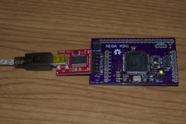
Nick Gammon’s Bootloader sketch to burn the boot loader to the ATmega. It’s the same setup I used to boatload the
MEGA MINI PCBs I made back in January.
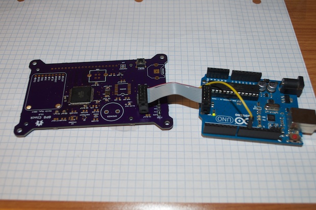
However, this time something is wrong. The bootloader took, and I don’t get any errors when I verify the chip. The problem is sketches do not upload to the chip via FTDI.
To rule out software, I grabbed my MEGA MINI and uploaded the Blink sketch. Good as gold.
I thought it was something to do with the board, but I double checked everything. The chip appears to be fine, so why won’t sketches upload? I tried it on 2 PCs and 2 Macs, but it times-out every time. The strange thing is that once the bootloader was written, the LED I have attached to pin 13 blinks twice, pauses, blinks twice again, and repeats. It looks like the chip is stuck in some sort of boot-loop. I tried to burn the bootloader again, but it timed-out when using my UNO as an ISP. Nick Gammon’s sketch worked, and passed verification, but sketches continued to time-out on upload.
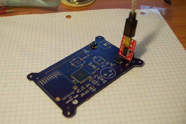
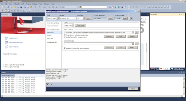
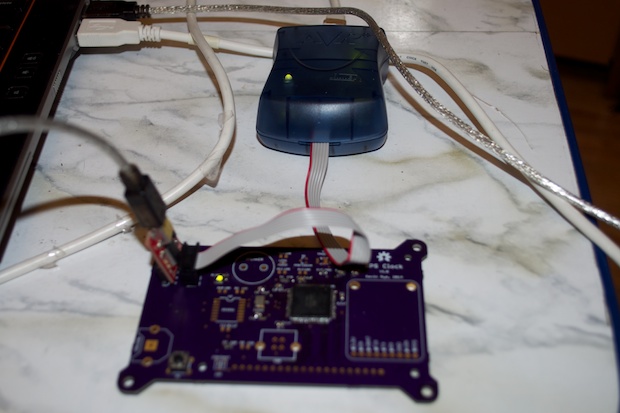
I figured I’d whip out my Windows laptop and try Atmel Studio 6. I connected my AVRISP MKII to the PCB, powered it off my FTDI breakout board, and fired up Atmel Studio.
I managed to burn the bootloader on the first try without any complications.
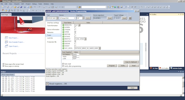
I set the fuses as follows:
0xFF // fuse low byte: external clock, max start-up time
0xDE // fuse high byte: SPI enable, boot into bootloader, 1280 byte bootloader
0xF5 // fuse extended byte: brown-out detection at 2.7V
I took those settings directly from Nick Gammon’s sketch. I know they work on the MEGA MINI, so they should work here too.
They took without incident.
Lastly, I set the fuse bits. Again, directly from Nick Gammon’s sketch.
0x2F // lock bits: SPM is not allowed to write to the bootloader section
No problem.
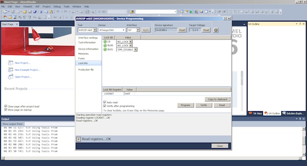
So far so good. It looks like everything took, and the LED on pin 13 isn’t flashing like it was before. I get the double-blink at power on, and then it stops.
I found a cool tutorial over at
Crash-Bang Prototyping that showed you how to toggle a GPIO pin on the ATmega328. I changed it a bit to flash pin 13 on the ATmega2560.
#define F_CPU 16000000UL
#include <avr/io.h>
#include <util/delay.h>
int main(void)
{
DDRB |= (1<<DDB7);
while(1)
{
    PORTB |= (1<<PORTB7);
    _delay_ms(1000);
    PORTB &= ~(1<<PORTB7);
    _delay_ms(1000);        /
}
}
I compiled the source and wrote it to the chip.
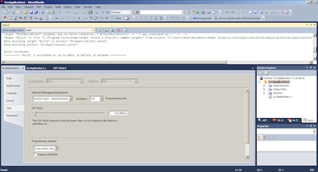
Boom! It worked on the first try. Bootloaded, and loaded with some code. It works!
It’s still a mystery as to why the Arduino IDE won’t work. The MEGA MINi works as well as my UNO. I was able boatload those devices and upload code. For some strange reason, it just does’t like the PCB. Which is strange, because it’s pretty much the same exact thing as the MEGA MINI.
Now knowing at least the chip works, I went ahead and soldered in all the rest of the components. (All except the GPS module.) I want to make sure that all the other hardware works and that I can upload my final sketch before soldering that in. I’d hate to hit and snag and lose a $40 GPS module.
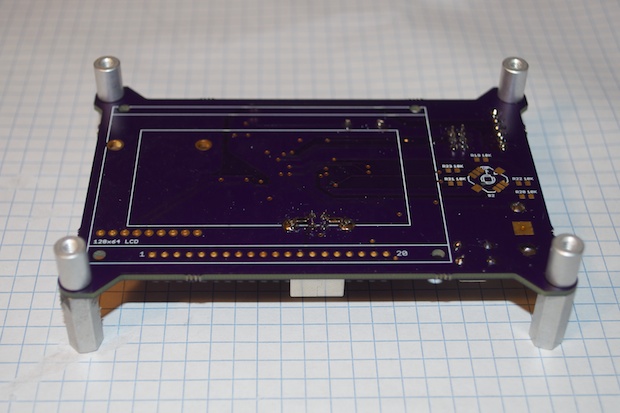
Since the USB port on the back sticks out a fair bit, I screwed on some board stands just to keep the PCB flat and stable while I solder in the 5-way switch and resistors.
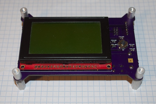
Lastly, I soldered in the display. Like I said, I didn’t want to solder in the GPS module unit I knew all the other hardware was working, but I just soldered in the LCD. How am I supposed to solder in the GPS board when I just covered the holes? Yeah, that was dumb.
I’ll figure out how I’m going to work around that when the time comes. I might have to unsolder the LCD. Then again, I’d rather cook a $20 LCD than a $40 GPS module.
I crossed my fingers and plugged it in. Nice. I still have a green blinky light. At minimum, I didn’t short anything out. The second green light (in the center) is connected to the audio amp, so I know it’s also getting power. There’s no data flowing yet, but at least I know it’s “on”.
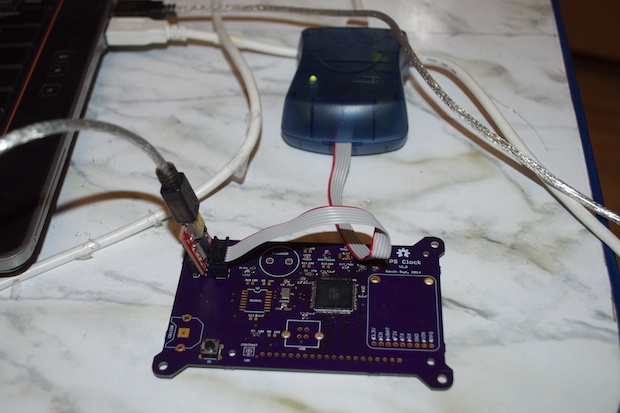
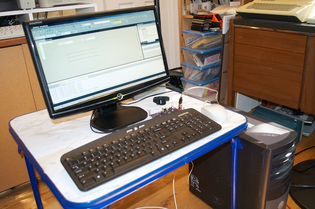
I dug out an old PC and installed Atmel Studio on it. It’s not looking good though. This PC is so old and slow, that it’s barely usable. I’d use one of the the kids’ PCs, but they’re not much better. The
last time I tried it, I couldn’t for the life of me get the computer to recognize my AVRISP mkII.
Still no luck. Both the Arduino and Atmel Studio just time out. I decided to take a step back and re-review my schematic.
I realized that I have FTDI connected to RXD1 and TXD1 instead of the usual RXD0 and TXD0. I wondered if that made a difference. Does FTDI only work on pins 2 and 3? I posted a feeler on the Arduino forums to confirm. Sure enough, that’s the case. The bootloader only looks at RXD0 and TXD0, and no other.
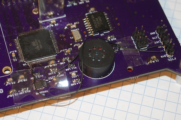
I decided to try and salvage the board. I’m going to redo the schematic and order a new board anyway, but I wanted to at least see if I could get this one to work. I soldered some really thin wires from the FTDI header to pins 2 and 3 on the ATmega. I then cut the traces that lead to pins 45 and 46.
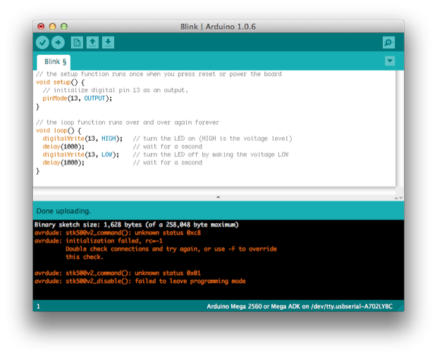
I fired up the Arduino IDE and attempted to load the Blink sketch. I got another error this time, but at least it didn’t time out.
I put in a valiant effort on this revision. I’ve spent the past week troubleshooting it to no avail. It’s time to cut my losses and order another board. I’ll just have to cross my fingers that it works.
See this project from start to finish: GPS Clock Prototyping, Part I GPS Clock Prototyping, Part II Arduino Mega 2560 GPS Clock Prototyping, Part III GPS Clock Prototyping, Part IV GPS Clock Prototyping, Part V GPS Clock Assembly, Part I
GPS Clock Assembly, Part II GPS Clock Assembly, Part III GPS Clock Assembly, Part IV GPS Clock Rework - Ditching the Joystick, Part I GPS Clock Rework - Ditching the Joystick, Part II GPS Clock Rework - Ditching the Joystick, Part III
