I admit it: I'm a total geek. I love electronics, programming, 3D printing, 3D art, and vintage Apple hardware. I'm always juggling half a dozen projects. I also enjoy documenting it all: my successes, my failures, my experiences... and everything geeky along the way.
GPS Clock Assembly, Part II | Kevin Rye.net - Main
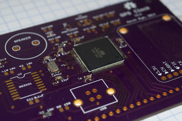
If you’re following along, you know that version 1.0 of my GPS clock was a total bust. I somehow managed to screw up the PCB. I had the FTDI RX and TX lines tied to the wrong port on the ATmega2560. There was just no way to rework the board. Besides, I like to keep my final projects looking neat and clean. Rework wires are just a big no-no in my book.
That meant that I had to fix the error on the PCB and place another order.
I just hope this does the trick. At $56.80 an order, this clock is starting to get pretty expensive. When all is said and done, I will have spent a good $200 in parts. Chalk that up as the cost of R&D.
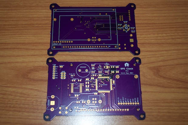
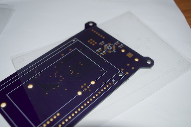
About 2 weeks later, my PCBs turned up, albeit one short. I put in a support ticket to see what happened. They claimed that the fab house marked the board as having an open circuit, so they opted to not ship it. It would have been nice if they had thrown a note to that effect in with my boards. Oh well. They then gave me a refund for the board, so I guess all is good.
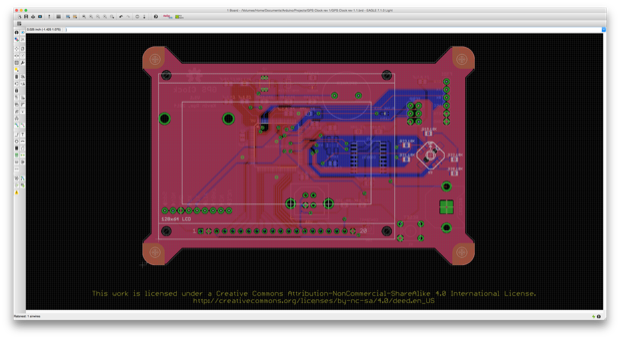
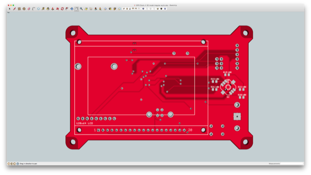
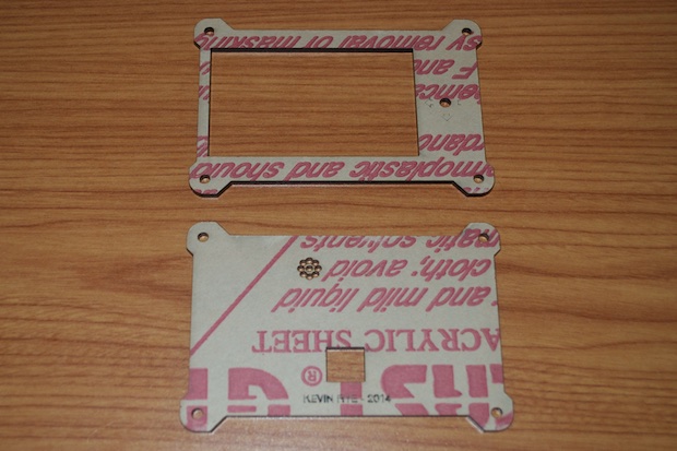
While my PCBs were being fabbed, I took the time to work on the laser-cut acrylic panels. I exported my PCB from Eagle to SketchUp.
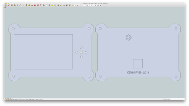
I then added a 2mm trim and holes for the LCD, USB connector, speaker, and 5-way joystick.
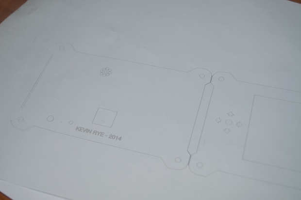
I printed it out on transparency paper to make sure everything lined up.
It’s so much easier to see that all the cutouts are in the right place with transparency paper.
I placed my order with Ponoko and patiently waited. About a week later, my acrylic arrived in the mail.
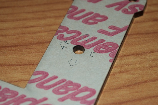
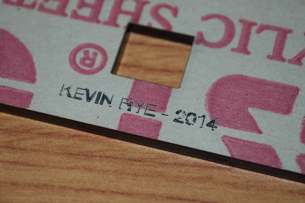
Apparently, I still haven’t mastered the fine art of raster engraving. I wanted my name as well as the arrows on the front for the 5-way switch to be fill-engraved. However, it looks like I messed it up again. I double checked my settings against Ponoko’s design guide. I just don’t know what I’m doing wrong. The lines are barely visible, and the shapes are definitely not filled. I might have a go at etching it with my Dremel. In the end, I’ll probably have to figure it out and place another order, because I guarantee that I mess the whole thing up with the Dremel.
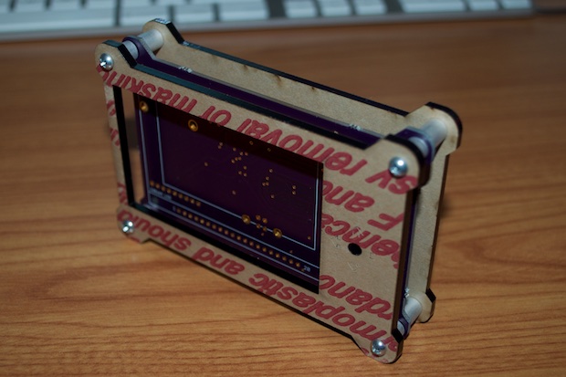
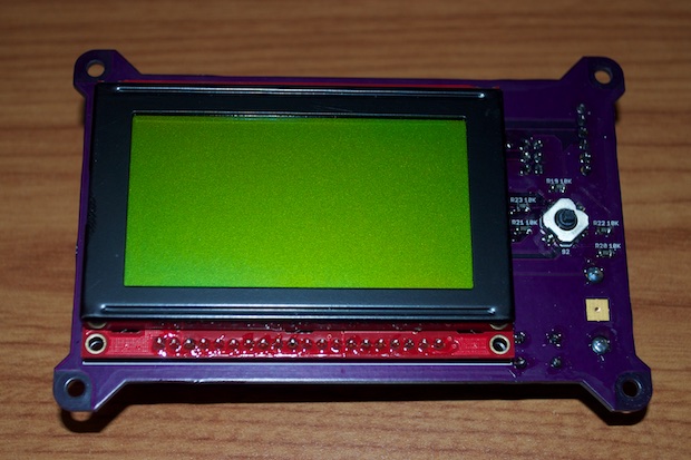
Just for fun, I assembled the whole thing together as a preliminary test. It looks like everything will line up to where it needs to be, but I probably won’t know for sure until I solder everything together.
Once my ATmega2560 arrived in the mail, it was soldering time! This one came out great. I’m really getting good at drag-soldering 100-pin chips!
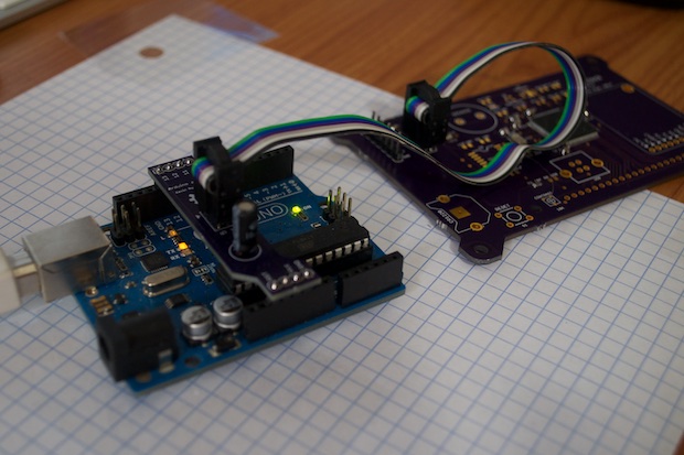
I only soldered together enough components in order to bootload the chip. I tried my Arduino as ISP shield but for some reason, the Arduino IDE threw an error. Subsequent attempts just timed out. I don’t know what happened there, so I opted to default back to Nick Gammon’s bootloader sketch and tried it that way.
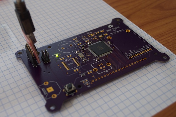
Success! It worked. I was then able to successfully upload the Blink sketch via FTDI. Looks like version 1.1 is a go!
I soldered in all the audio components and then uploaded the Tone sketch to try it out.
Success again! Since the speaker is so small, I had to crank the gain on the audio amplifier to the max. It’s still not incredibly loud. I’m not using it as an alarm clock, I just want it to simply “beep” on the hour. I cranked the gain on the video too so that it’s a little louder than normal.
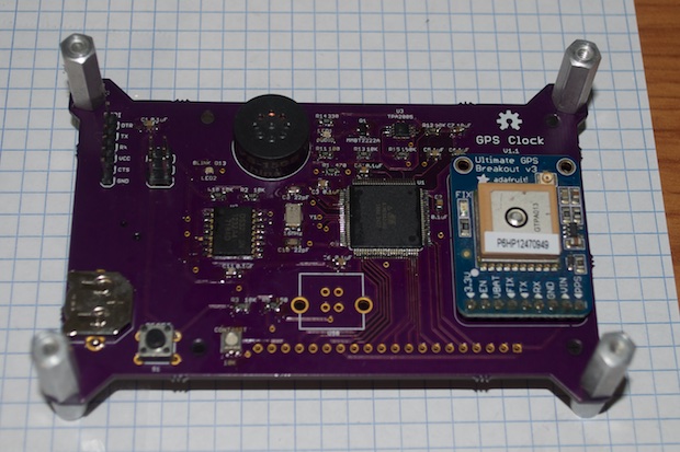
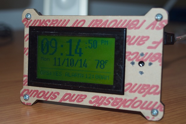
I soldered in the GPS board and the DS3231 RTC and uploaded a sketch. I got it to spit back the time, so it looks like everything is working.
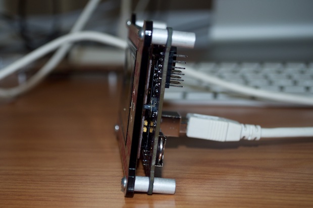
Lastly, I soldered in the 5-way switch, the resistors, the USB connector and the LCD.
I totally nailed the acrylic panel. It fits perfectly.
But as I suspected, I made a mess of it trying to touch up the arrows with my Dremel. I’ll have to make another one. At least I know the footprint is good.
I also need to design some sort of knob for the 5-way switch, as well as finish the code. It’s not over yet!