I admit it: I'm a total geek. I love electronics, programming, 3D printing, 3D art, and vintage Apple hardware. I'm always juggling half a dozen projects. I also enjoy documenting it all: my successes, my failures, my experiences... and everything geeky along the way.
Driving a Nixie with a 74141 BCD Decoder | Kevin Rye.net - Main
I could just jump right in and start working on a nixie clock, but I want to start off small and learn all that I need to in order to design my own. Anyone can copy a schematic and load some code, but will they know how and why it works? I like to completely understand how things work, this way I can make my own from scratch on not just carbon-copy someone else’s design.
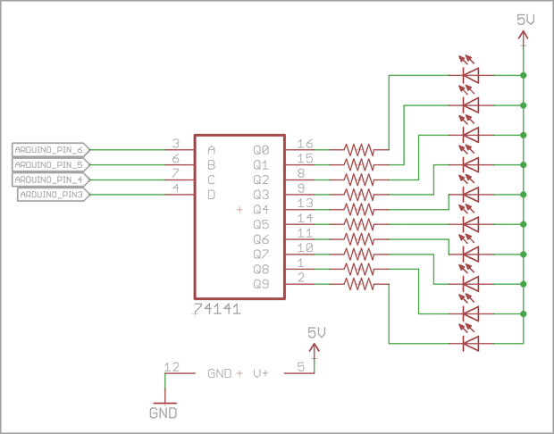
In order to drive a nixie, you can use a 74141 BCD decoder. Sure, you can use transistors, but you’ll need a bunch of them. You can drive all 10 nixie segments off one 74141 chip. All you have to do is feed it a number in binary and the chip lights up the corresponding cathode on the nixie; the same way you’d drive a 7-segment display with a 74247.
To start out small, I’ll use LEDs just to test the chip and my code. It’s just a simple sketch to count from 0 to 10 in binary. In theory, each LED should light up one at a time.
Here’s the schematic:
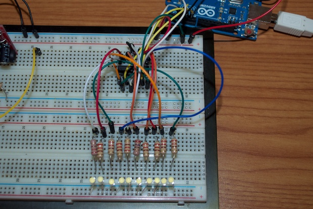
I hooked up all 10 LEDs to the 74141 and loaded my sketch.
All the sketch basically does is toggle 4 output pins HIGH and LOW to simulate a binary number on the 4 input pins of the 74141.
int a = 6;
int b = 5;
int c = 4;
int d = 3;

void setup() {
  pinMode(a, OUTPUT);
  pinMode(b, OUTPUT);
  pinMode(c, OUTPUT);
  pinMode(d, OUTPUT);
}

void loop() {
  output(0,0,0,0);
  output(0,0,0,1);
  output(0,0,1,0);
  output(0,0,1,1);
  output(0,1,0,0);
  output(0,1,0,1);
  output(0,1,1,0);
  output(0,1,1,1);
  output(1,0,0,0);
  output(1,0,0,1);
}

void output(int d, int c, int b, int a) {
  if (a == 1) digitalWrite(6, HIGH);
  else if (a == 0) digitalWrite(6, LOW);
  if (b == 1) digitalWrite(5, HIGH);
  else if (b == 0) digitalWrite(5, LOW);
  if (c == 1) digitalWrite(4, HIGH);
  else if (c == 0) digitalWrite(4, LOW);
  if (d == 1) digitalWrite(3, HIGH);
  else if (d == 0) digitalWrite(3, LOW);

  delay(500);
}
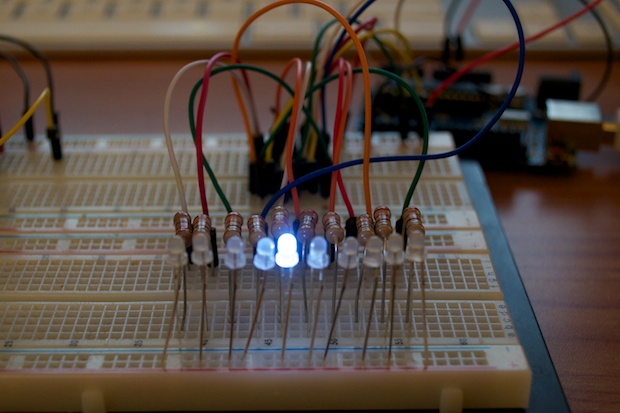
Cool. It works. Each LED lights up as the Arduino counts to 10.
Better yet, here’s a video showing it in action:
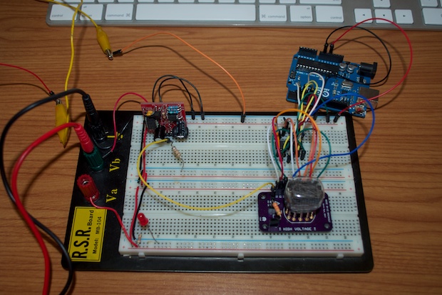
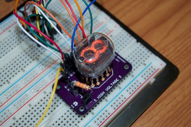
It’s then just a matter of swapping out the 10 LEDs for a nixie. Here’s the schematic:
I connected the anode to 170 volts and each cathode to the corresponding pin on the 74141.
And there it is. It counts!
Again, another video to show it in action:
In the end, I’ll probably use some 74595 shift registers to push all the data to my nixies, but for now, I’m off to a good start!