Nixie Clock 5V / 12V Power Supply
Jun 23, 2015 Filed in:
Electronics | NixiesThe past few months have seen zero progress in the nixie clock department. The clock took a backseat to some
other projects that I wanted to wrap up, not to mention the new ones that I started. I still haven't finished painting my
3D-printed Mei Lin statue. In any case, it's time to dig back in and make some progress.
The power supply I picked out to step my input voltage up to power the nixies runs off 12 volts. That introduces an additional task of having to step the voltage down to 5 volts for the logic. I immediately defaulted to the tried and true 7805 voltage regulator. After chalking up the design and laying out the PCB, I realized that the heatsink it would need to keep cool would be way too big and run way too hot to cram into a small clock enclosure. I'm also not about to incorporate a fan into a desk clock.
I needed to find an alternative to the classic 7805. I decided to go with a super small buck converter. I found one on eBay for $3 bucks. It even has a trim pot so you can adjust the output voltage all the way down to 1V. The best part is that it doesn't need a heatsink. I picked up a few in case they come in handy for other projects.
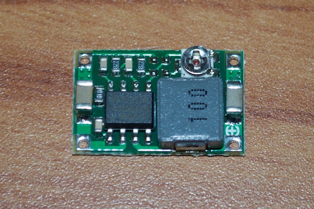
It really is tiny and I have more than enough space on my PCB to fit it in. It only measures 11x17 mm.
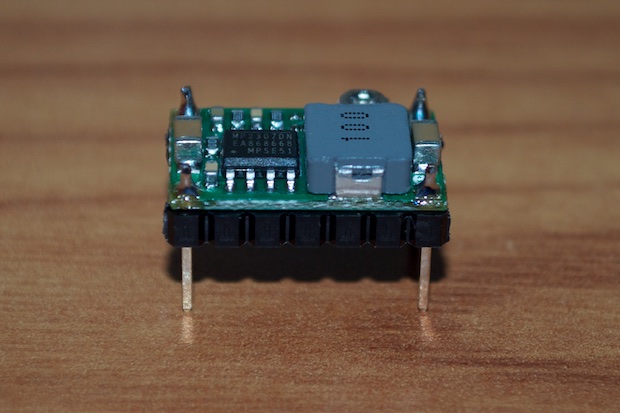
I soldered some headers onto one so that I could breadboard it.
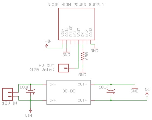
I put together a schematic to try it out. Twelve volts comes in from the wall wart and powers the nixie supply and the buck converter. The buck converter takes the 12 volts and knocks it down to 5 volts for the logic. The nixie supply steps up the 12 volts to 170 volts that'll feed the nixies.
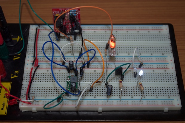
All that was left to do was throw it on the breadboard and try it out. I threw in an LED and a power transistor so that I could test out the 5 volts. I put 5 volts on the base of the transistor to turn on the nixie. Everything works.
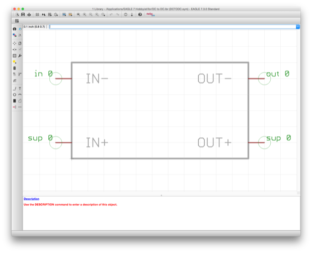
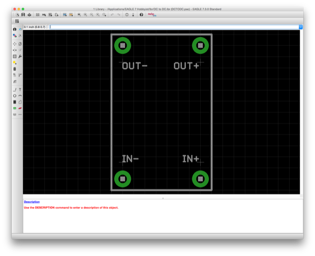
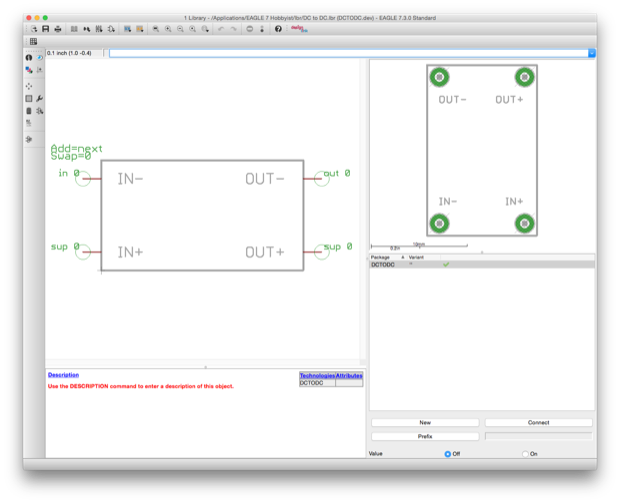
I even made an EAGLE part for it.
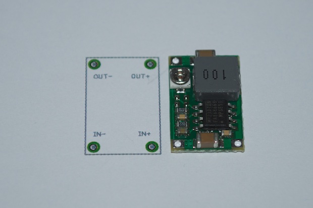
I printed it just to make sure everything lined up. It's perfect.
Now I just have to design the PCB.
See this project from start to finish: Nixies! Got My Nixies Powered! IN-12 Nixie Breakout Board, Part 1 Flashing a Nixie with an Arduino IN-12 Nixie Breakout Board, Part 2 Driving a Nixie with a 74141 BCD Decoder More Nixie Tube Experiments Nixie Clock 5V / 12V Power Supply
Nixie Clock PCBs / EAGLE Upgrade Nixie Clock Main Board PCB Build Nixie Clock Final Build, Part I Nixie Clock Final Build, Part II Nixie Clock Final Build, Part III Clock Button Panels
